Those rechargeable reading lamps are really nice, a pity they don’t last longer. But you can make them. It’s super simple – just add a second rechargeable battery.
These lamps are being sold by a couple of different Chinese manufacturers. Some have only one type of LED, some have two – for different lighting colours – and they all have a touch-sensitive top as power switch, charge via USB-C port, and are 40cm high.
And they seem to have one other thing in common: they have room for a second battery. At least the three different types I opened did.
It doesn’t get any easier: Order battery, solder connector, insert…
Some of them even have a second battery charger terminal, like the one I modified in the video. Others don’t; there you can just add the second battery in parallel or, if you are less adventurous concerning the charging circuitry, remove the first battery.
The battery type used is a standard single18650 Li-Ion cell; rechargeable, with 3.7V voltage. The lamps usually hold one of those, offering 2400mAh of charge, but there are also affordable types that last longer, like this Samsung INR18650 with soldering pads (no affiliate link, order them wherever you like.) Just ordered a couple, as I am also planning to upgrade my new Digitakt.
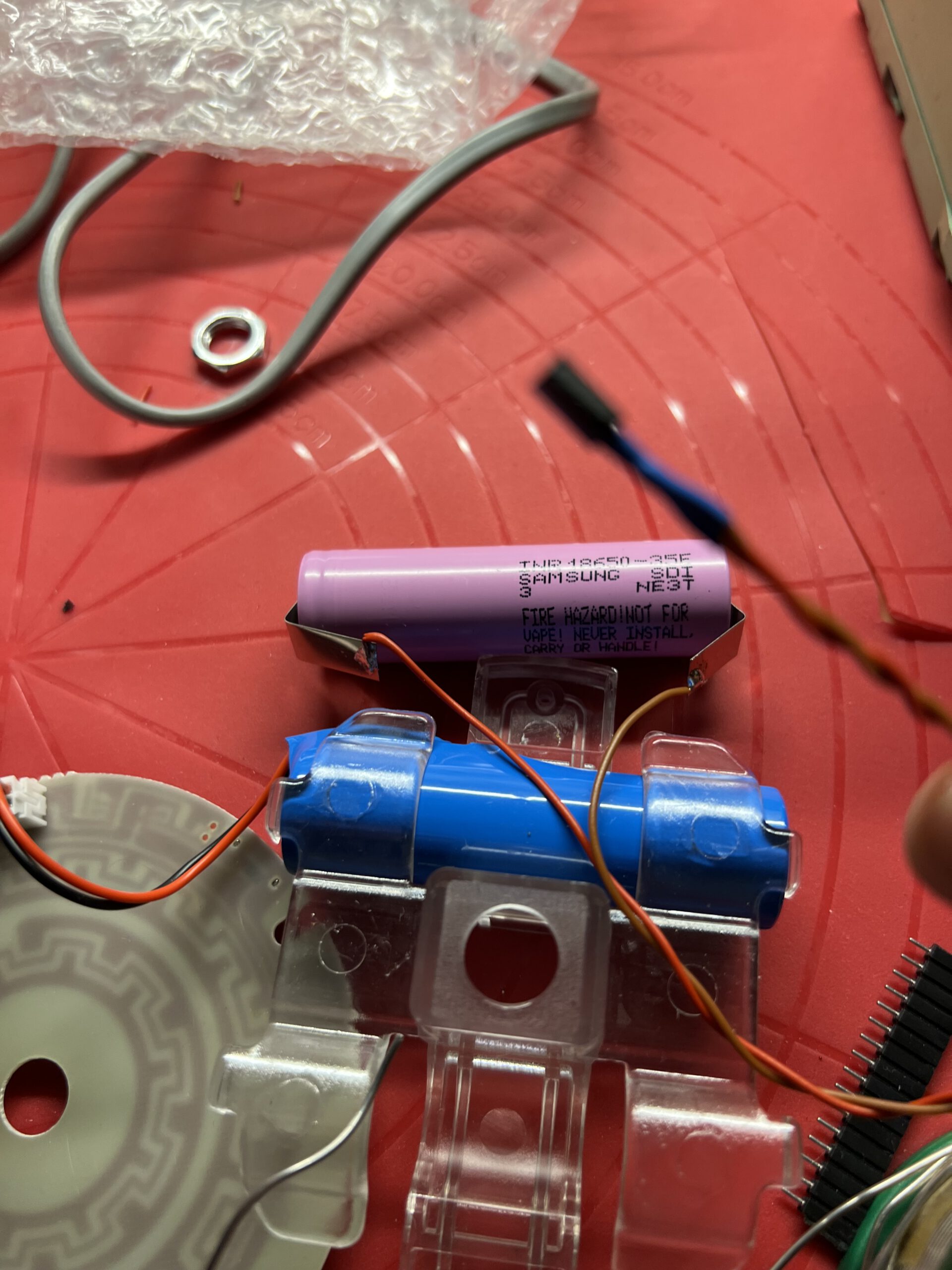
So this is about as simple as it gets: open lamp, unpack battery, solder connector to the battery without overheating it – this is where the solder pads come in handy – remove first battery, plug in connector, test lamp, plug in second connector, test again, reassemble lamp, make wife happy.
…and I hadn’t realized that you can dim them!
It is a bit embarrassing but it took a hint from my daughter for me to realize that these lamps also have a dimmer function. If you keep your finger on the touch-sensitive switch, the brightness will decrease, then increase.