(I wasn’t willing to translate that myself; GPT-4 generated translation. German original here.)
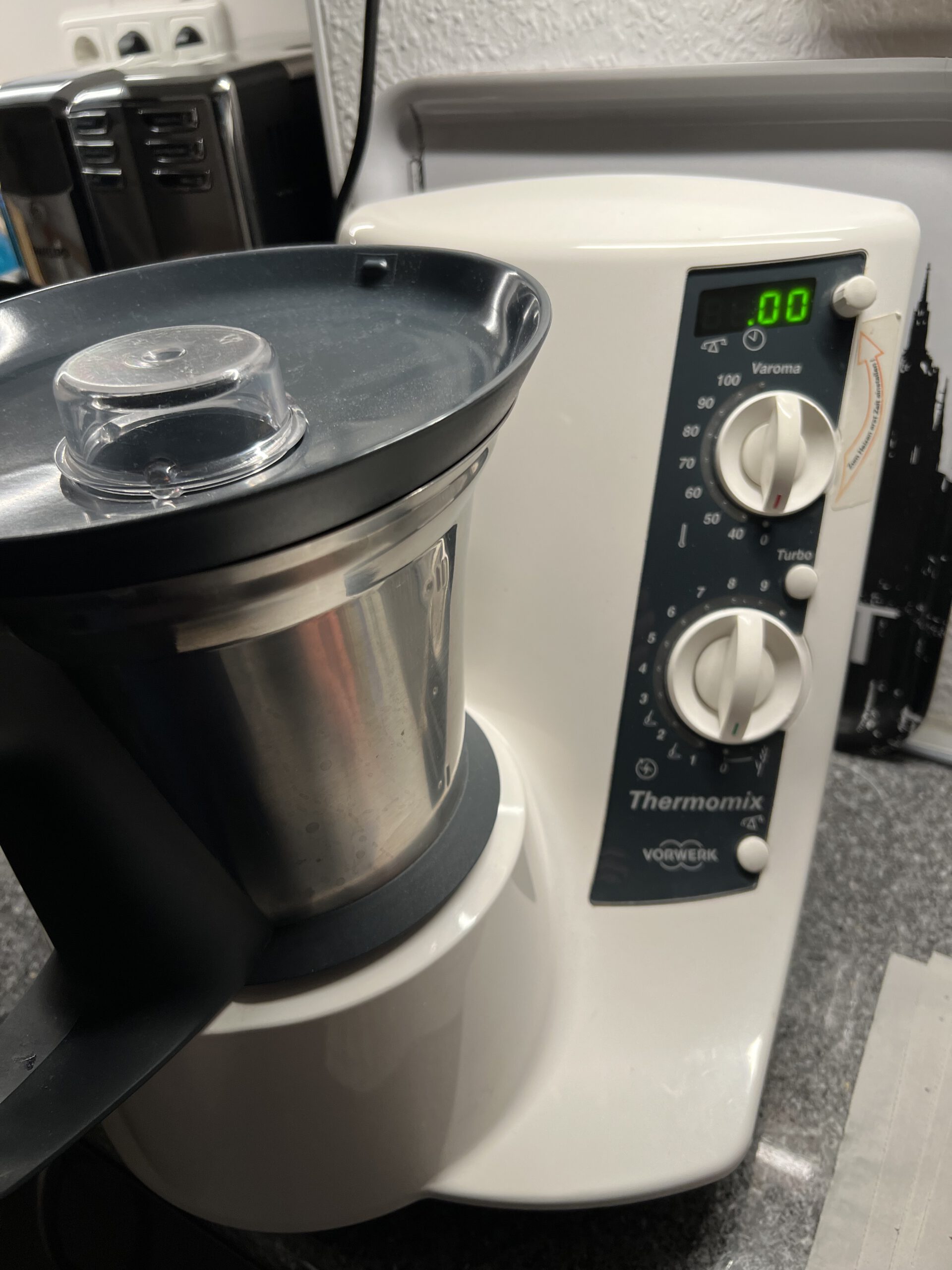
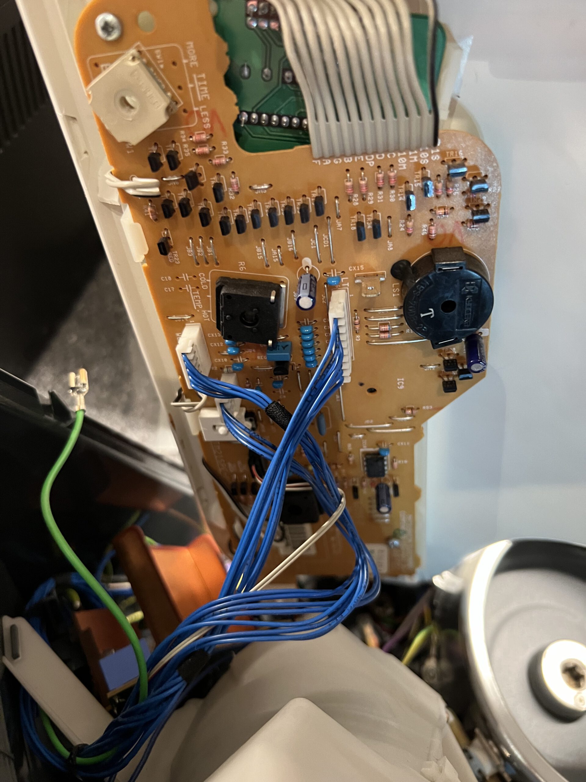
Blick unter die entfernte Oberschale; Kabel noch gesteckt
Unhooking and Folding Away the Upper Casing Shell
Next step is to unhook and fold away the upper casing shell. Disconnect the cables from the electronics – there are three white flat connectors with blue wires in different sizes, one black (with two grey cable cores), and the contact shoe of the green grounding wire. Once these are disconnected, you can remove the entire upper shell from the device.
Buggered those Push Buttons!
These can be tricky. That’s why it’s a good idea to watch a tutorial first.
Understanding the Push Buttons Mechanism
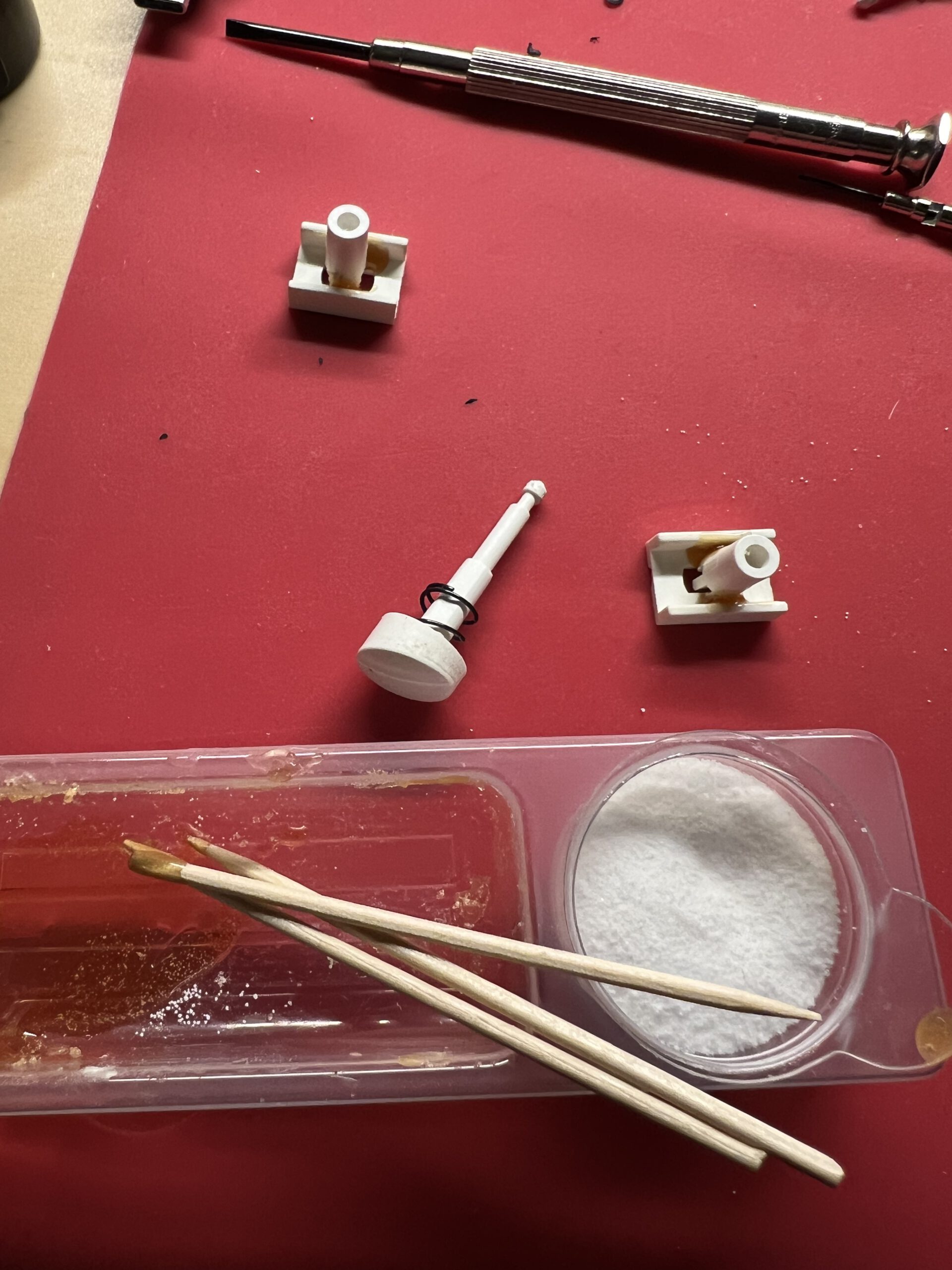
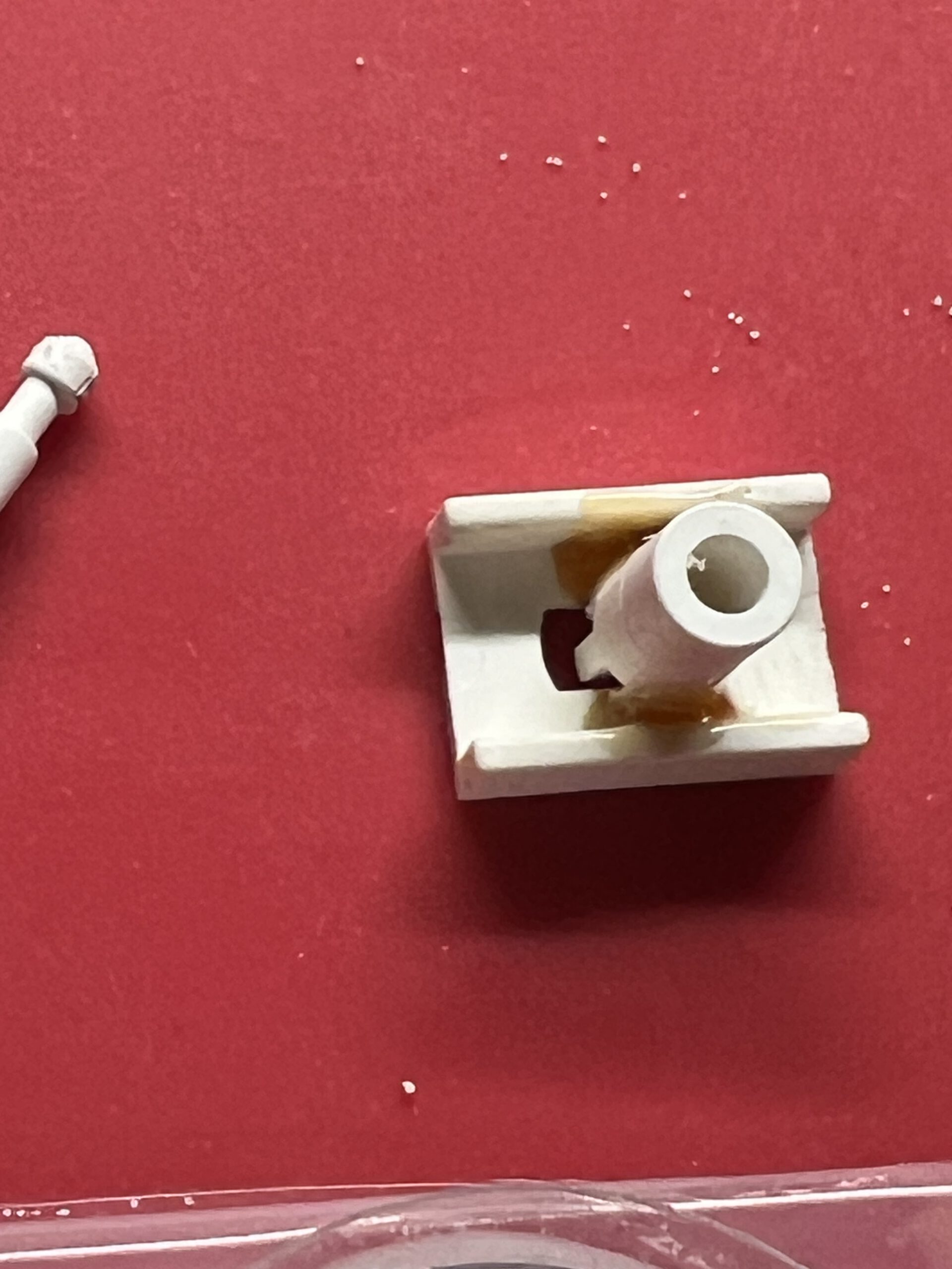
The push buttons are comprised of two main parts: the actual button, which protrudes from the front of the casing with a pin attached to it, and a counterpart that keeps the switch contact closed as long as no one presses the button. To remove the button, you need to detach the top part from the pin. That much is clear.
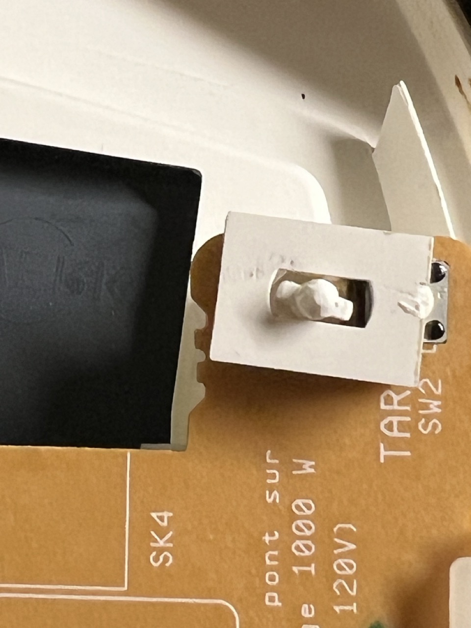
Unfortunately, the only solution I could think of was to use force, which led to me tearing off the rectangular plate on top. (This plate presses the switch.) It’s flanged to a tube where the pin goes, and at its upper end – visible through the slit below the plate – there are two small arms that hold the pin. You need to spread them apart using two small watchmaker’s screwdrivers, then you might be able to pull out the pin. Maybe.
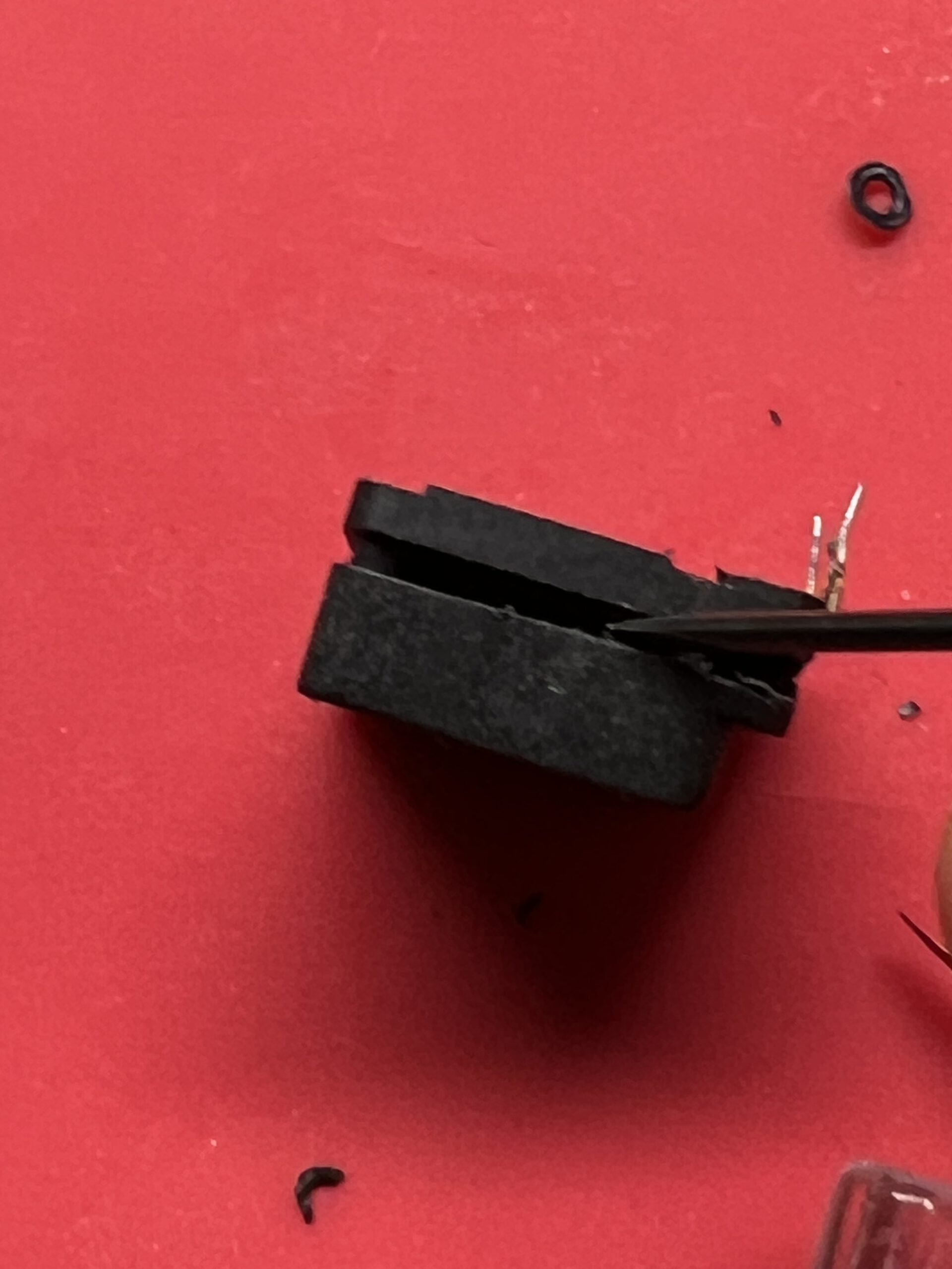
Or, it might end up looking like this – the part in the middle and the one on the right are actually supposed to be connected; I ended up brutally tearing them apart.
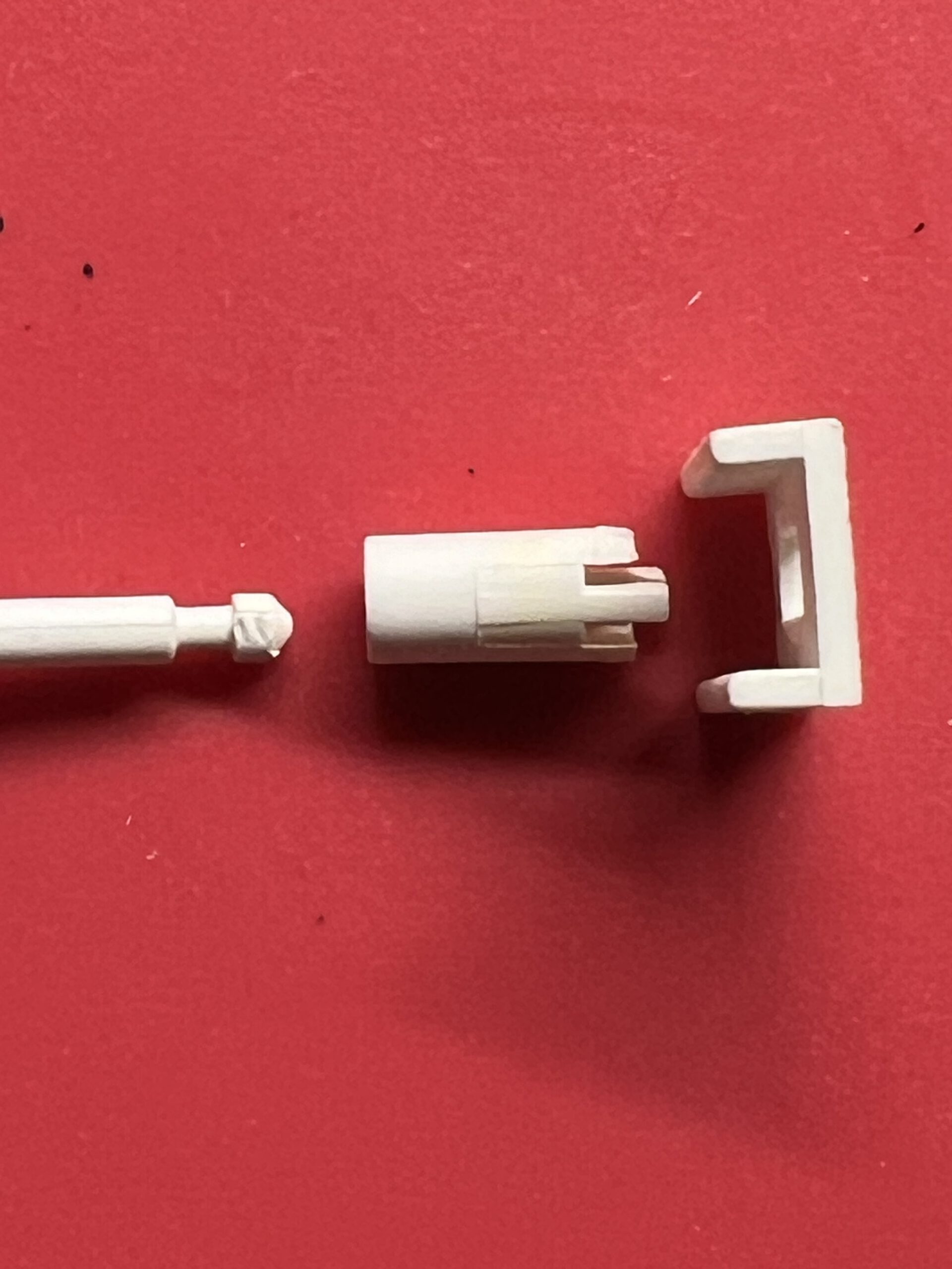
I resorted to the reliable two-component adhesive. It worked after reassembling, and I hope it holds permanently, though I’m not very confident. If I can’t find replacement parts, maybe I’ll 3D print them, or else I might just permanently attach the plate to the pin.
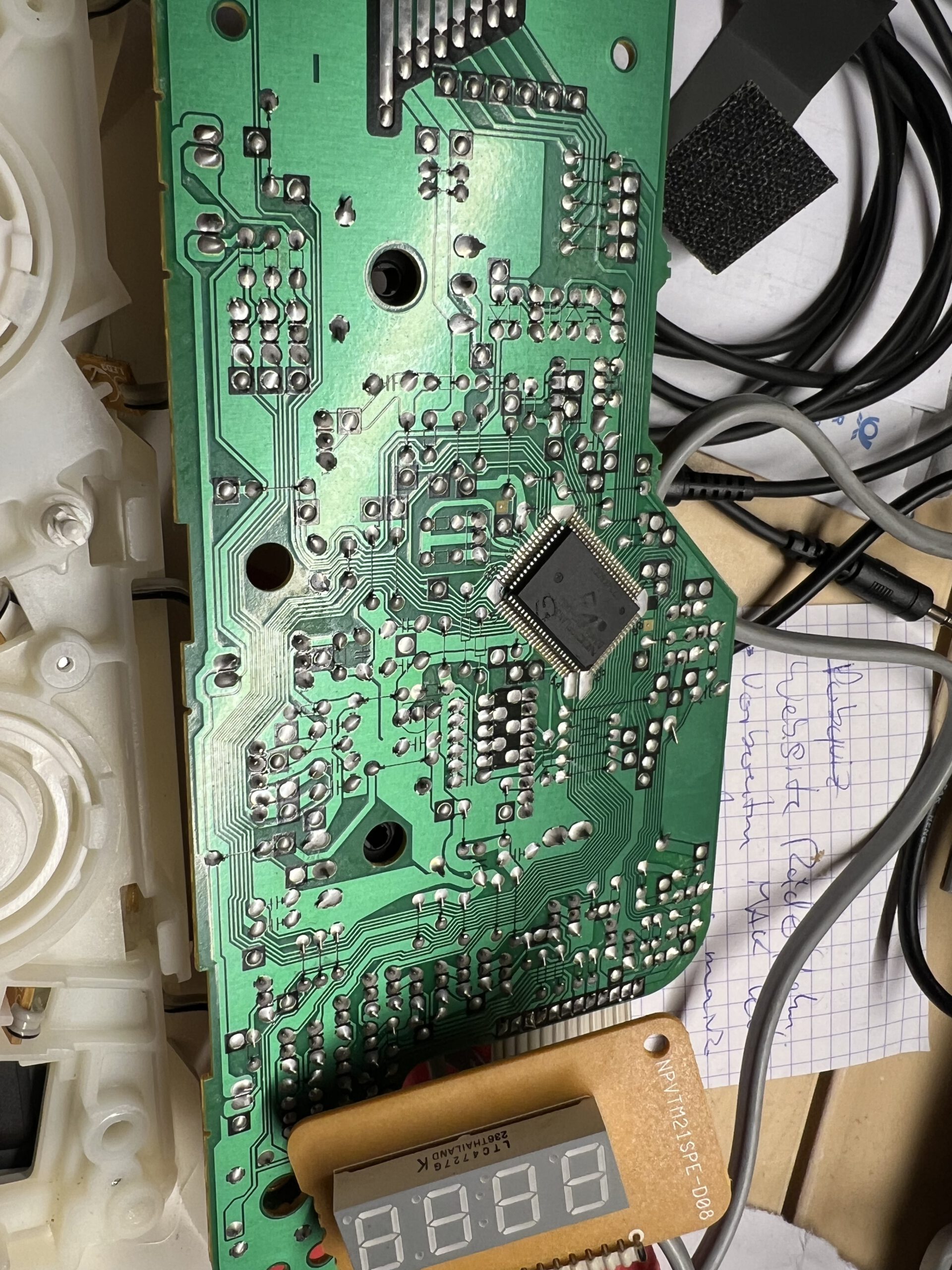
Next, unscrew the three screws from the circuit board and unhook the display, which is held in place by two plastic tabs. Then, remove the electronics.
The potentiometers are soldered at three contacts as usual and additionally held by two tabs that are inserted through the housing and bent over. Carefully unbend these, lift the three poles of the potentiometer, and remove it.
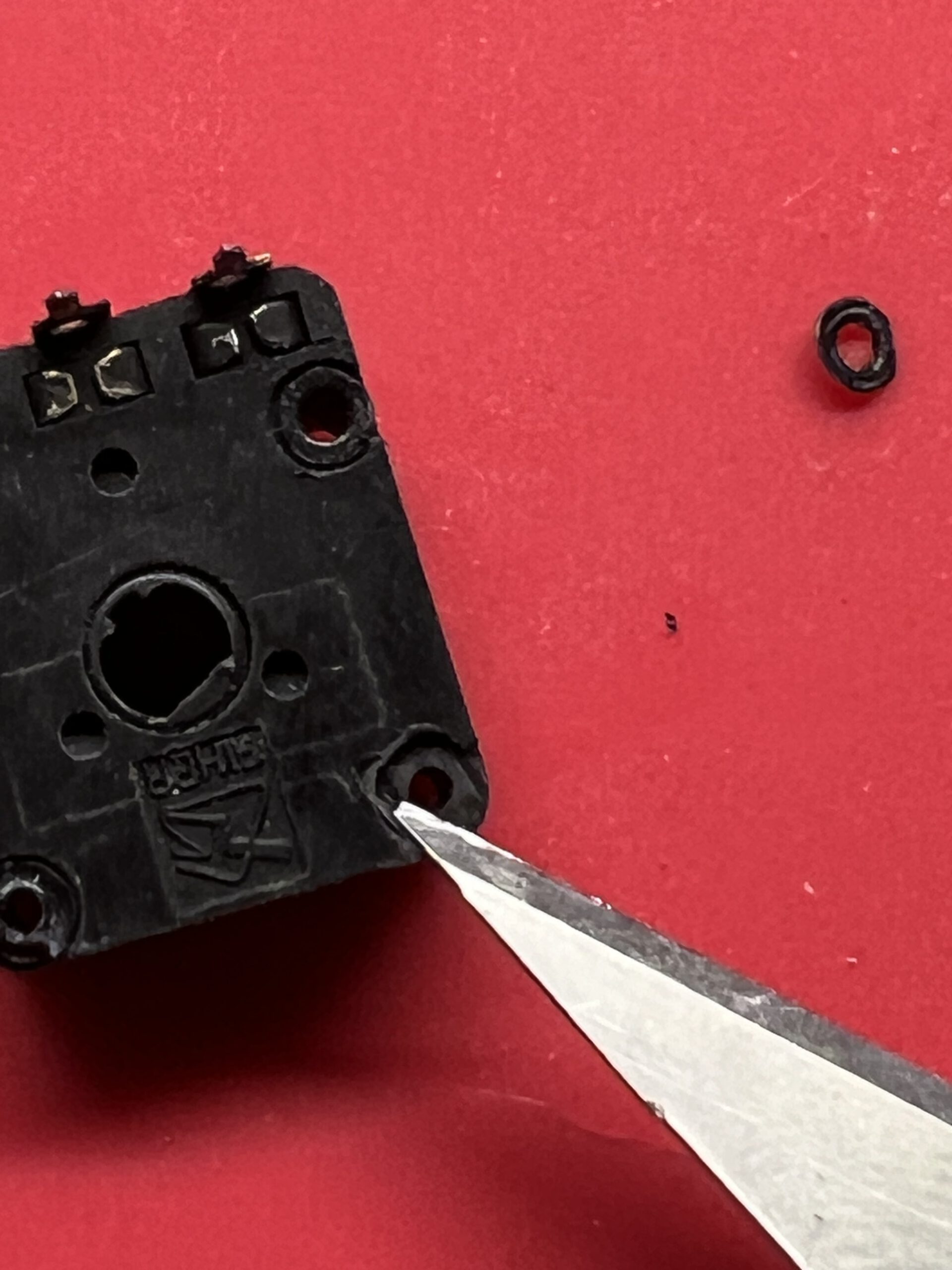
It’s a 22k potentiometer from Piher. I couldn’t find a replacement part quickly, so I decided to open it up. (Update: I’m trying with a Pipher PT15NH now; that’s the closest approximation I could find with that through-hole shaft. Piper datasheet here.)
The cover is pressed onto the housing from the bottom and riveted over four plastic pins; you have to cut these slightly with a scalpel, then the cover can be pried open.
With the potentiometer open, do what one does with open potentiometers – clean the wiper and track with isopropanol or mild alcohol, gently bend the wiper contacts back into shape, and – I am grinding my teeth while writing this – apply a little contact oil, if available. Absorb any excess oil, reassemble the potentiometer, solder it back in place, bend the tabs back, and it’s done.
Reassemble everything – and it works.
Vielen Dank für die Anleitung, hat mir sehr gut geholfen. ich hätte etwas kaputtgemacht ohne Deine Sehr gute Beschreibung.
Viele Grüße
Matthias
Danke, freut mich sehr!
Hallo,
vielen Dank für die ausführliche Beschreibung!
Noch habe ich mich nicht an den Thermomix ran gemacht, aber ich bin mir sicher, ohne Anleitung würde ich etwas kaputt machen :-)
Bei meinem Gerät hüpft die Zeit wirr hin und her, wenn man an Regler oben dreht.
Hast du einen Tipp was da kaputt ist?
hilft an der richtigen Stelle eventuell etwas Kontaktspray, oder muss man einen neuen Drehregler einbauen?
Ferndiagnosen sind natürlich immer schwierig, aber vielleicht gibt es schon Erfahrung bei diesem Problem.
Danke & Grüße
Johannes
Klingt sehr nach einem in die Jahre gekommenen Encoder.
Hm, hm… am besten ist natürlich, das Vauteil zu tauschen, aber wenn kein Ersatzteil greifbar ist, hilft vermutlich auch: Encoder aufmachen, Schleifbahn putzen, den Kontakt ein wenig nachbiegen – und wenn’s unbedingt sein muss, etwas Kontaktspray, aber das richtige! (im Prinzip so wie hier beim Blofeld-Synthesizer. :)
Hi, I tried following the guide, but I still get the annoying beeping no matter what, and the motor doesn’t start
Afaik it’s a board problem. Do you have any tips?
Cheers
As always, I would go and check the sensors. Have a look at the switch that is closed when you put the lid onto the cup; it’s in the bottom of the Thermomix. That caused problems in ours, and to be honest, we decided that we would start no further attempt at repair. But it’s perfectly feasible. A damaged switch might cause the very problem you describe.