This is the first post in a series of small projects for retrofitting my JEN SX-1000 monosynth with a simple and cheap MIDI interface controller. Read about the basic idea here. Today, I am designing and building the micro-controller brain of the Jenny retrofit – if you are capable of basic soldering, it should not take you more than two hours and a couple of very common electronic parts.
The object of this sub-project is to design and build a small interface PCB for a microcontroller to replace the JEN’s one truly digital component – the M110 divider/keyboard scan circuit. Doing a breadboard version of this interface should be feasible in about an hour, a single-sided PCB will be done later. And once this works, you might even be able to make a small profit by selling the M110 chip on eBay!
What we will do, and what we won’t
- This will be a functional replacement for the M110 chip in the JEN.
- It will scan Jenny’s keyboard and put out the matching square waves, generated as divisions of the (analog) master clock.
- It will generate the negative /GATE (-TS) and /TRIGGER outputs the JEN needs
- It will not yet generate a correct VCF tracking – additional circuitry, or at least adjustment of the JEN’s filter tracking preamp, may be needed to do that
- It will not yet take heed of the Glide Pot input – the glide circuit is actually a small oscillator, the frequency of which determins how fast the generated frequency is counted up/down to the next note
- It will not yet listen to, or send, MIDI – although this is no big deal
- It will not yet drive a display
- It will not read the Jen’s knobs, or generate control voltages – this will be done with a daughter board later on.
The part list
The parts are all easy to get online and in your local electronics store:
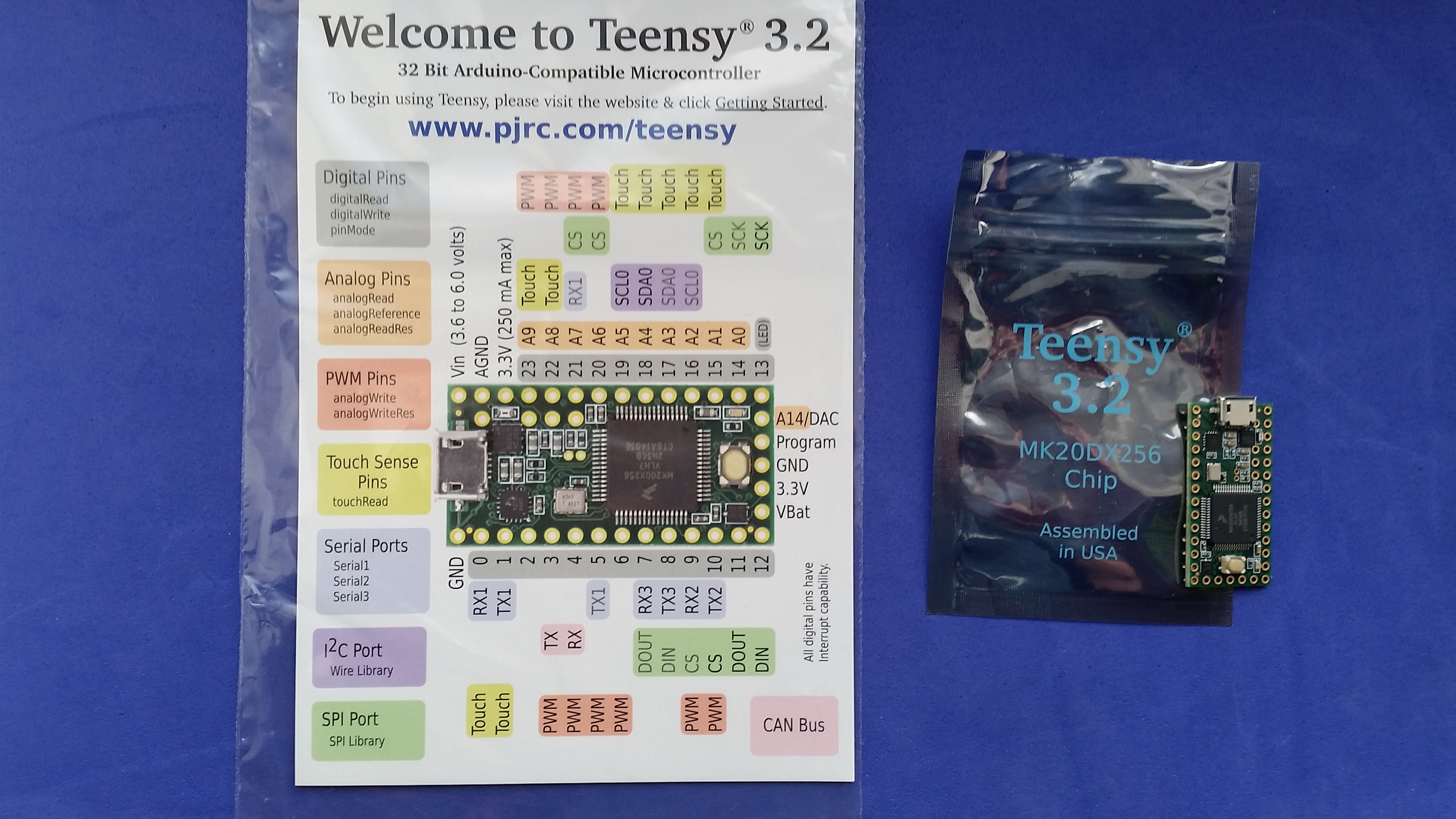
- 1 Teensy 3.2 micro-controller (about €20)
- 2 4-pin pinstripe sockets for MIDI and SPI/display connection
- 1 CD4504 level shifter CMOS IC (~€ 0,50)
- Two 3V3 Zener diodes
- Two 10k resistors
- 2 20-pole pinstripe connectors for connecting to the M110 socket
- 2 14-pin pinstripe connectors and matching sockets for the Teensy
- 1 breadboard
- Bits of wire
The Microcontroller
I decided to use the Teensy 3.2 – Teensys cost as much as the widely-used Arduinos but feature more input/output lines, a dedicated Digital-Analog Converter (DAC), and more processing power. It can be used with the Arduino programming environment which means that you have access to the very rich work of the highly active Arduino community, and can save lots of work by, say, using the MIDI library. Talking of MIDI: It is much easier to turn a Teensy into a MIDI USB device than an Arduino. I paid €20 for a Teensy 3.2, and you can even find them on Amazon.
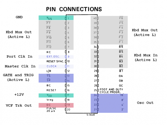
Comparing the Teensy 3.2 input/output layout with the M110 socket, I thought that by rotating the Teensy, an interface board can be very simple. Most M110 signals – all of the keyboard scan lines, for example – can just be soldered to the corresponding pin, directly or over a resistor.
A couple of Teensy pins should be reserved for expansion and dedicated functions:
- Pins 2 (D0) and 3 (D1) for MIDI In/Out,
- Pin 20 (D13) as the clock input – to feed the JEN’s oscillator into one of the Teensy’s timers, enabling you to do the frequency division in hardware rather than software
- Pins 25 and 26 (D18/A4 and D19/A5) for an I2C interface – we need this to drive the display
- Pin 19 (A14/DAC) – the dedicated DAC output voltage for the VCF tracking output.
JEN modifications necessary
My original target was a small board that you could just slot into the M110 socket without soldering, but you can reduce the complexity of the board enormously by two simple operations, both confined to the keyboard PCB:
- cut out the 5.6k pullup resistors to +12V for the four keyboard multiplex lines used (thereby saving interface circuitry for twelve keyboard scan lines)
- connect the interface board to a +5V line (thereby saving the need to use a regulator to generate the +5V supply for the Teensy board).
Levels
Wiring the new world to the old world leads to conflict in signal levels. The Teensy 3.2 operates at 3.3V, with a tolerance for 5V input. Most of the JEN’s electronics are old-school CMOS chips running on 12V, expecting and producing high signal levels above approx. 7V, and low signal levels below 3V. The M110 is run on 12V. This is more than the Teensy chip can handle.
The Teensy’s inputs are easily protected by a voltage divider – two resistors, say, 10k and 2.7k – or a resistor and a Zener diode (more here in this Instructables tutorial). There are actually only two inputs that have to be converted down from 12V to 3.3V – incidentally, they are both clock inputs.
With the digital output levels, it is a bit more tricky: According to the data sheet, the Teensy’s MK20DX256VLH7 chip outputs 0..0.5V as L, and VDD-0.5V as minimal H – as the Teensy is running on VDD=3.3V, this would be 2.8V; not enough to switch a CMOS chip at 12V. The levels have to be converted. Neil Johnson uses a ULN2003 driver chip with pullups for level conversion; I am using a cheap, old-school CD4504 CMOS. Both chips are easy to get, and cost a few cents.
The Teensy board will, at a later stage, have to control analog signals. Most analog control voltages in the JEN may range from -12…+12V, so the 12-bit DAC output of the chip, which puts out values between 0.1 and 3.3V, has to be converted to that range with an opamp, and de-multiplexed, to have more than one control voltage available. We will do that in the next step.
I will break down the signal interfaces in signal groups:
Keyboard Scan multiplex Lines
Keyboard scanning is done by stepping through the twelve keys of each octave, setting the active line to L. If the key is pressed, the corresponding scan input is drawn L as well. No interfacing needed, provided… see below.
Scan lines F1 to F6 (M110 pins 35-40) are interfaced to D7-D12 (Teensy pins 9-14), scan lines F7 to F12 (M110 pins 2-7) are interfaced to D14-D17, D20-D21 (Teensy pins 21-24, 27-28).
Keyboard scan inputs
The M110 offers six lines to scan up to six-octave keyboards, but with the JEN’s 37-key keyboard, only four of them are in use. They are pulled up by 5.6k resistors, which we cut from the keyboard PCB, as we will be using the Teensy’s internal input pullups.
Once the removal is done, no interface circuitry is needed for these inputs.
Timer Inputs
The only two inputs that actually need levelling:
- The VCO master clock input (M110 pin 11 -> D13, pin 20) – a square wave of approx. 2MHz at 12V level. (Which is a pity because this VCO is actually a TTL IC running at 5V, followed by a transistor to convert the signal to 12V level. Neil Johnson bridged the transistor, I’ll step the signal down again to avoid soldering within Jenny.) Converted to Teensy-appropriate levels with a Zener diode and a resistor.
- The Glide circuitry input (M110 pin 9 -> ) – the Glide pot does not feed a voltage, or current, to the M110, but a frequency that is used to increment/decrement the frequency towards the next note. Converted to Teensy-appropriate levels with a Zener diode and a resistor.
OUtput Waves
Four square-wave outputs for the four footings, 16′ (D27 -> M110 pin 24), 8′ (D28 -> M110 pin 23), 4′ (D29 -> pin 22), 2′ (D30 -> pin 21). Using part of the CD4504 level shifter will do the trick.
I am aware that I am wasting three perfectly good digital outputs by creating the lower footings in software rather than with a simple CD4024 CMOS counter, like Neil Johnson did it, but I am trying to keep it as simple as possible. Maybe later on.
Control Lines
Two active-low outputs for the /GATE (D6, pin 8 -> M110 pin 13) and the /TRIG (D23, pin 30 -> M110 pin 14) signal, used to control the envelopes. Interfaced over two CD4504 gates.
Analog Output
As mentioned above, this output will be analog-multiplexed later on. For the time being, a small amplifier raising the level to 12V will do.
The Timer
The Freescale MK20 chip on the Teensy 3.2 has three very versatile timers called “Flexible Timer Module” (FTM). Unfortunately, you cannot use them. It is not possible to clock them via an external source – as the Freescale engineers had the brilliant idea of routing the external clock input to the same pins needed for the system oscillator crystal, all you could do is re-solder the Teensy board and equip it with an extra oscillator circuit. Forget it. And they are not equipped to count timer overflows either, so you cannot tweak another FTM’s control line into a counter input.
Luckily enough, the MK20DX256 chip has another timer called “Low Power Timer” (LPTMR) that can be configured to “Pulse Count” mode – counting pulses from an external input. And this input can be routed either to one of the XTAL pins – brilliant idea, see above – or to – TA-DAAA!!! – pin 13, the one controlling the LED.
To my big surprise, the LPTMR module actually does have a mode where it counts pulses up until a compare value is reached, and then issues an interrupt. So yes, you can use it as a divider to generate the four output clock footages depending on the key pressed.
In case you should ask: The JEN’s master VCO clock runs at 2MHz.
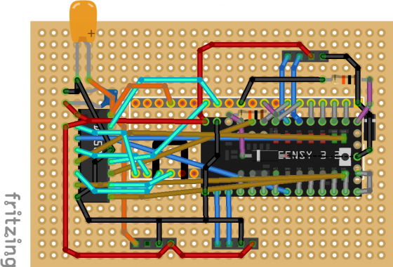
Keep It Simple, Stupid: A Teensy interface board
With all that in mind, an interface board might look like this:
Firmware
A short program should be enough for testing the board in the synth, done without interrupts for the time being: The code runs a loop scanning the keyboards, then calculating a divider value for the LPTMR counter. The interrupt routine has the humble task of incrementing a 4-bit counter, effectively putting out the four output footages as square waves.
I am going to put a sketch into a Github repository.
Future enhancements
Although the Teensy can, in theory, read analog signals on 20 pins, I think it is better to do input multiplexing – with the method used 30 years ago: a couple of 4051 analog switches will provide us with more analog inputs, and control voltages. This will be done with a (De)MUX daughter board with those cheap 16-pin CMOS chips, in a later sub-project.
If you use a simple prototyping breadboard, you should have enough room left for expansion – and there are two important things we are leaving out at this stage:
- The interface board does not read the Glide control. As the Glide circuit actually produces a frequency rather than a control voltage, a method of interfacing the Glide pot to the Teensy has yet to be designed (other than just cutting up the Glide circuitry and wiring the Glide pot directly to the Analog input).
- The interface board does not yet output a control voltage for VCF tracking. This is a small loss – not only synth technology god Gordon Reid noted that Jenny’s tracking circuitry is annoying. Further research has to find out how much of the existing circuitry could be repurposed, and develop a tracking calibration routine.
Make sure that there is room left for, say, a small 8-pin TL081 op-amp, and a few more capacitors and resistors.
If this design works, and has been updated to include the two features described above, it should be easy to do a cheap and easy single-sided PCB.
Pingback: MIDIfying Jenny - A Call To Arms - untergeekuntergeek
Hey, is it possible that this built can be completed? I guess it lacks the Midi I/O board, doesnt it?
It is possible but I guess I won’t be doing it anytime soon. Haven’t made any progress in the past four years, so…
Hi,
very nice start, which could be pushed forward collectively in github, even without your efforts.
Could you also share the draft code you used for testing ?
Thanks,
Elum
I will, although there isn’t much to upload yet (and hell knows where I will find it). Jenny as an upgrading project is far back in the queue of projects to do which keeps getting longer and longer… :)
I feel like the DAC could also be used to generate the audio oscillator output, as it tends to die in these unobtainium M110 chips.
Maybe multiplexing could allow to drive the VCF + to generate the oscillator output, if not then upgrading to Teensy 3.5 would probably be enough, with it’s 2 DACs.
Cheers,
Elum