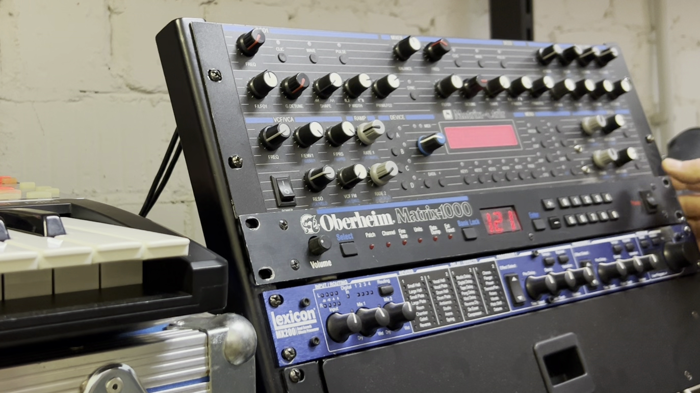
It’s analog, it’s compact, it’s enduring, and it’s still just about affordable: Oberheim’s budget synth expander from the company’s dying days sold by the truckload—and remains a cult favourite on the second-hand market, though not too cult. Let’s crack open the Matrix-1000 and see what this 40-year-old hardware can (and can’t) do. What should you watch out for, and what can modern tech do to drag it into the 21st century?
Forgive me for inserting a slice of analog synth porn here:
Although the Matrix-1000 is nearing 40, it’s very much alive and kicking. It’s an analog that you can still, kind of, afford – and, more important, that still works. The Matrix-1000 ROM is by far the most popular firmware of all the upgrades Bob Grieb ever designed; they must have sold loads of that synth. And they have survived to this day, the occasional battery failure or dying voice chip nonwithstanding.
The very quality that made it a cheap, second-rate option back then – its lack of immediate controllers – is no longer a problem. When I bought my Matrix around 1990, I was stuck to the presets; these days, MIDI controllers are easy to find.
As a couple of people have asked about recommendations for controllers, you will find a collection of options I came across. It is worth noting that most of them work with the earlier Matrix-6/6R version of the synth as well although it lacks the option to use NPRN as well as dedicated commands to control the modulation matrix. Continue reading →
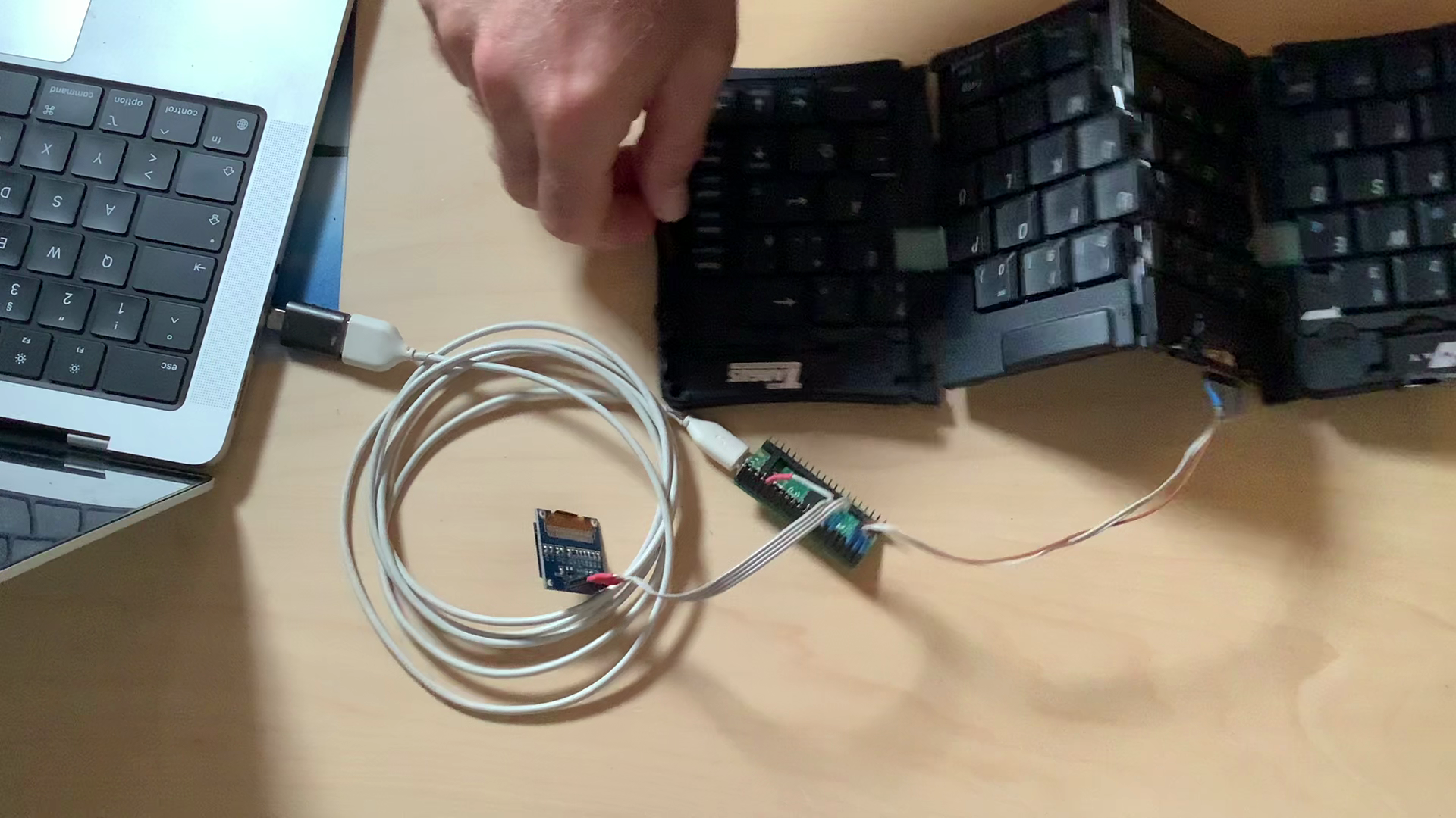
A small project to reconnect an old Targus Stowaway Handspring keyboard with the modern computer world, and learn some more Raspi Pico Python in the process.
To start with the bad news: The answer is probably no. (Betteridge’s Law holds.) But it may be good to know that there are possible options for an internal upgrade of the Reface speakers, and that the Reface speakers aren’t really that bad (albeit tiny). So please stay with me.
An option for setting voice allocation in the Matrix simply does not work – never has – and nobody seems to have noticed up to now. But there’s a fix for that.
“Hey, I want that update! Especially as I already own V1.20!” — PLEASE READ HERE
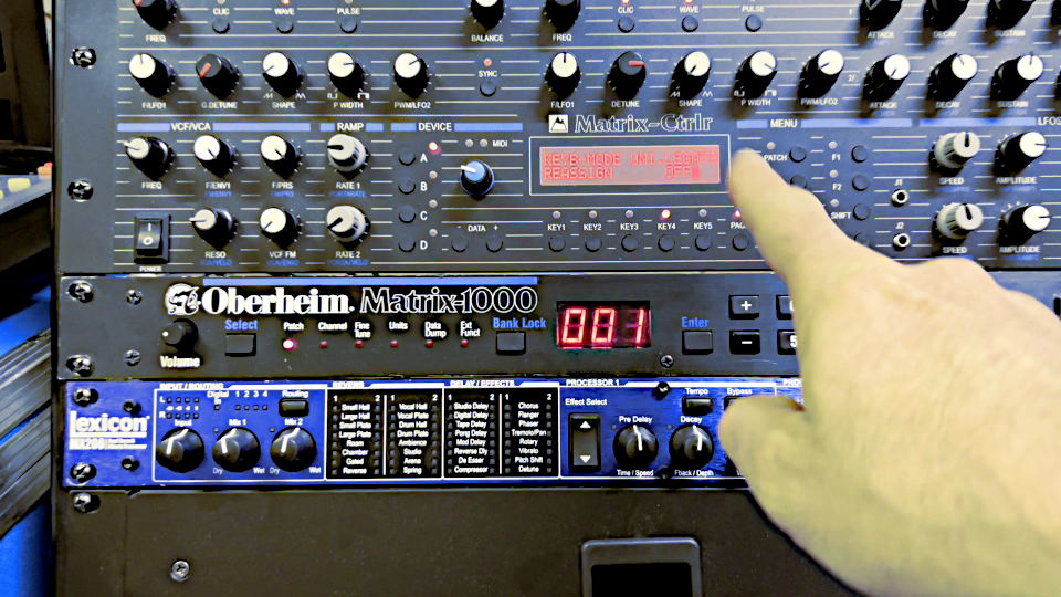
A couple of days ago, Bob Grieb – the engineer behind the Matrix-1000 update I am selling here – got a email from a Matrix owner using the updated V1.20. The mail politely noted that the “Reassign/Rob” setting wasn’t working, and inquired whether there might be a problem with the V1.20 firmware. Bob, who does no longer own a Matrix-1000, fired up a Verilog simulation he had created for testing, and found that the Matrix owner indeed was right – the “Reassign/Rob” setting of Parameter 48 (0x030h) wasn’t working, and it wasn’t working in firmware V1.13 either – a very early patch of the last factory firmware by Oberheim itself.
So it was a bug that had always been there, and nobody seems to have noticed. Or, at least, have cared enough to look for a fix.
What “Reassign/Rob” is supposed to do – and why you never noticed
The Matrix-1000 has six voices. When your Matrix is playing six notes at once, it won’t accept any new notes unless you release one of the notes being played. This is the default setting, and it comes in two flavours, “Rotate”, and “Reassign”. They are set with values 0 and 1 of parameter 48, and the Matrix-1000 manual also has two more settings, Unison (all voices playing at once), and “Reassign/Rob”.
The Matrix-1000 manual is a bit cryptic about the meaning of all this; quoting from the Matrix-6 manual instead:
ROTATE: When playing notes on the Keyboard, this polyphonic mode loops through the six Voices assigning each new note to next available voice.
REASGN: Abbreviation for “Reassign”, this polyphonic mode is similar to ROTATE but notes that have the same pitch (otherwise known as “note value”) are reassigned to the same voice. For example, if you play Middle C it will be assigned to a certain voice. Every time thereafter when Middle C is played on the Keyboard, that voice will play. “Reassign”, by the way, is the KEYBOARD MODE enabled in the Basic Patch.
UNISON: This mode takes the MATRIX-6 out of polyphonic mode and makes the synthesizer monophonic.
(…)
REAROB “Reassign Rob”: When in Reassign (REASGN) mode, voices will be robbed from keys held in the same way as ROTROB.
So what the “Reassign/Rob” value actually is supposed to do, is to enable voice stealing — notes being played suddenly go missing, making it painfully obvious that your synth is running out of resources. It is infuriating when we notice, and we seem to notice the limitations of a 6-voice synth a lot more when notes suddenly vanish than when they never appear in the first place.
So to be honest, I never noticed that this doesn’t work. Did you?
Bob, however, found the reason: The code for the note-stealing setting is 3, but there is a safety check that limits the parameter to entries from 0-2 instead of 0-3, so that the correct value can never be received. It’s only one byte that has to be changed – no, one bit, actually: Look for 0x81 0x02 0x22 0x02 in the ROM and change it to 0x81 0x03 0x22 0x02; changing one lousy bit. It’s that simple. And this is what we decided to call V1.21.
V1.21 is displayed on powering up
So how do I get it?
Unfortunately, this means that we will have to throw all V1.20s away, we cannot correct them. The one bit we have to change cannot be reprogrammed, so to upgrade from V1.20 to V1.21, you have to create a new chip, send it, and swap it.
And this is the main reason we don’t give the update away – this needs chips, and this takes work, so we charge you what is basically just the price of the chip and a fiver for programming it, and one Euro for Bob. We had a similar deal for Matrix-6 V2.14 owners when Bob discovered another bug that had always been hiding in the Matrix-6 firmware — and I hope you think that this is fair, because it is: after all, the bug wasn’t Bob’s fault, so he is in no obligation to fix it for free.
One last thought: ask yourself whether voice stealing is really worth the hassle. I know perfectly well that it’s quite possible to go GASsing for a software update, but: If you haven’t noticed the bug before, you probably won’t need the patch.
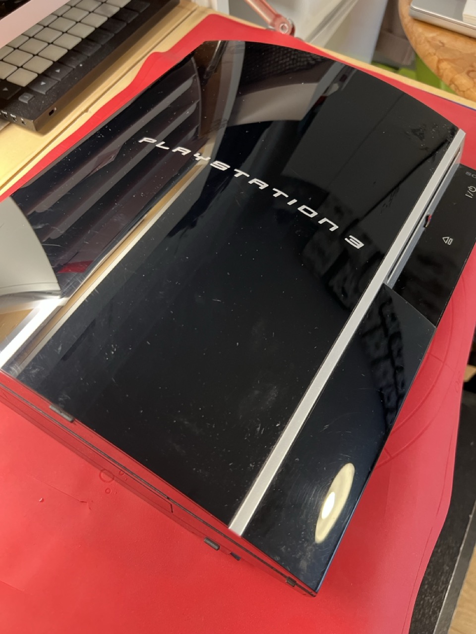
The PS3 is amazing – I got it 16 years ago, and it’s still running, working as a Blu-Ray player, and for the occasional round of Little Big Planet with the kids. And Sony still sends updates! But I noticed the fan has been getting rather loud, so I guessed it was time to clean the cooling paths.
In the end, it took me about 30 minutes to take it apart and put it back together again, due to Sony’s service-friendly design. And it wasn’t quite as bady in need of some cleaning as I feared.
The Waldorf Iridium is, amongst many other things, a sampler. And so many instruments have already been sampled – you will just have to load the samples to the Iridium, and place them in a patch.
This post will try to create a patch with the sounds of a Yamaha CP70 electro-acoustic piano, and have a small script do most of the work. If you are kind of lost here, read the “Not-so-grand-piano” post first.
The Waldorf Iridium is a great synth — and it is also a sampler. This is a tutorial for creating a multi-sampled piano sound from the factory samples, and having a computer program do most of the work of allocating them.
Looking at the analytics, I have noted that my reminiscence to/analysis of the Keytek CTS-2000 synth has been found by a number of people that surprises me, given that it is an article about a truly horrible, obscure late-80s hybrid synth in a rather niche blog. Given that, I would like to share some proof that I actually played that thing, and on stage, too. And though it is hard to date the old photographs, I would estimate that I held onto it for quite some time.
So I guess at least the CTS-2000’s keyboard was really decent.
The band, by the way, was named “Voice of the Alien”. You won’t find anything Googling it.
This website uses cookies to improve your experience. We'll assume you're ok with this, but you can opt-out if you wish.AcceptRead More
Privacy & Cookies Policy
Privacy Overview
This website uses cookies to improve your experience while you navigate through the website. Out of these, the cookies that are categorized as necessary are stored on your browser as they are essential for the working of basic functionalities of the website. We also use third-party cookies that help us analyze and understand how you use this website. These cookies will be stored in your browser only with your consent. You also have the option to opt-out of these cookies. But opting out of some of these cookies may affect your browsing experience.
Necessary cookies are absolutely essential for the website to function properly. This category only includes cookies that ensures basic functionalities and security features of the website. These cookies do not store any personal information.
Any cookies that may not be particularly necessary for the website to function and is used specifically to collect user personal data via analytics, ads, other embedded contents are termed as non-necessary cookies. It is mandatory to procure user consent prior to running these cookies on your website.