This JEN SX-1000 belongs to Stéphane in France, who wrote to tell me of the three mods he did. I have never seen two of them before – a Tremolo control, and variable filter tracking. Which would make Gordon Reid very, very happy.
So here is Stéphane’s letter:
“Hello, here are some modifications for the Jen synthetone SX1000. Nothing is disconnected. Components are added.”
(1) Bandwidth
“A capacitor of 200 microfarads is put in parallel with the input capacity of one microfarad of the filter. Advantage is taken from a strap near a potentiometer.”
Forgive me (untergeek) for interfering – this is one of the basic mods every JEN owner should do, using a larger capacitor for the filter input to better Jenny’s frequency response – keep the filter from killing the bass frequency. The charm of this variation is that there is no replacing involved, just soldering in a parallel capacitor.
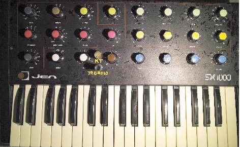
It is time to take a look at Stéphane’s modded panel – the mods are all quite economical and easy to integrate into the synth without ripping it apart. Which also means that they are easy to reverse. All the more impressive for what they achieve.
(2) Keyboard tracking
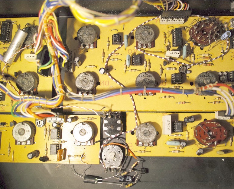
“A variable resistor of 2.2 megohms with switch, equipped with a limit resistor of 100 kilohms, is put in parallel with the one megohm output resistor of the main oscillator. The link is made by the twisted pair of red wire and white wire seen on the picture.”
I didn’t quite understand what he was doing here, so here is Stéphane’s (slightly edited) follow-up explanation: He points to the resistor network summing up the filter control currents at the input of the half-353 stage for filter control.
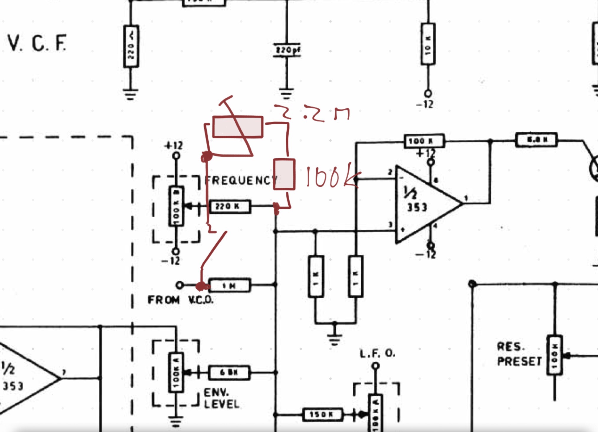
I did a quick schematic for the mod: Adding a 2.2M pot in series with a 100k limiter resistor in parallel to the 1M resistor limiting the tracking current.
“Different resistors of hig value act as current sources [for ENV LEVEL, FREQUENCY, L.F.O, and FROM V.C.O, which is the tracking voltage from the M110 chip]. The summation is done in the left 1 kilohm resistor of the input pair of the 353 ampliOP stage.
“Decreasing the 1 megohm resistor “FROM VCO” increases the effect of keyboard tracking. [..] When the tuning of the filter is tuned to follow the keyboard (you may use white or pink noise for that), the resonant filter may be used as an additional oscillator.”
Gordon Reid finds that the default tracking in the JEN is something like the “1/3” setting in a Minimoog which makes it unsuitable for using the resonant filter as additional oscillator. This mod enables the player to circumvent that problem, although the JEN still suffers from defective tracking which is not linear for the whole keyboard range; seems to be an inherent problem of the M110 chip that produces the tracking control voltage. But Stéphane has a hack for that.
[Non-linearities in the tracking] with respect to some parts of the keyboard may be hidden by a bit of LFO on the filter.”
“It is a quick modification that enhances the instrument the most in my opinion because a resonant filter is truly interesting when it is tuned to the fundamental harmonic.”
There may be alternative ways to do that hack; I’d prefer a simple switch between no tracking, 1/3, 2/3, and 1/1. Maybe it could also work on the double 353 OpAmp stage amplifying the current from the M110 for filter control.
(3) Tremolo
“The control signal (12 volts peak-to-peak centered at the ground) is led from the output of the low frequency oscillator to a 100 kilohms potentiometer through the ‘ribbon snake’ white-brown wire seen on the picture.”
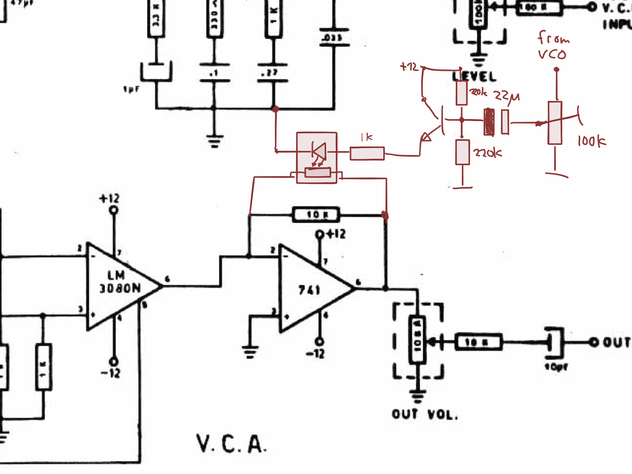
The schematic for the Tremolo mod as Stéphane did it – basically a homebrew opto-coupler to modify the amplification with the LFO, with an NPN transistor as a driver stage.
“A green 5 mm LED is fed by the emitter-follower transistor through a one kilohm resistor. In front of the LED is placed a 5mm photoresistor connected in parallel with the 10 kilohms feedback resistor of the output amplifier.”
Truly yours, Stéphane Grognet.”
Thanks Stéphane – I can’t wait to try it out! And I guess there will be others to follow you.