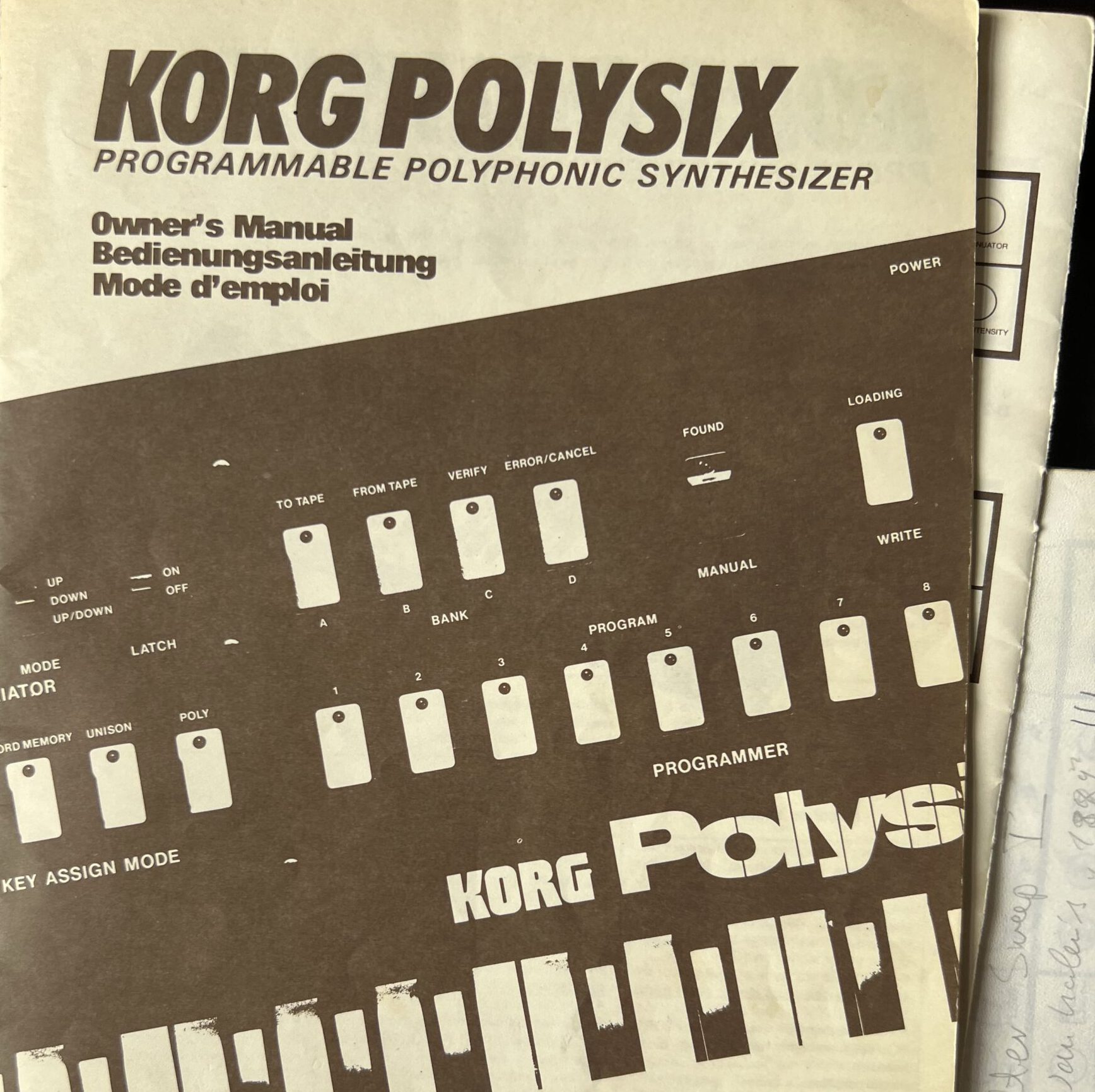
Getting hold of a piece of synth history, and a piece of my own history as well. And fixing it is just like everybody tells you it is.
Getting hold of a piece of synth history, and a piece of my own history as well. And fixing it is just like everybody tells you it is.
I’ll just put this on the Internet in case somebody else is searching for a solution to this problem which I couldn’t find anywhere, although it’s fairly easy:
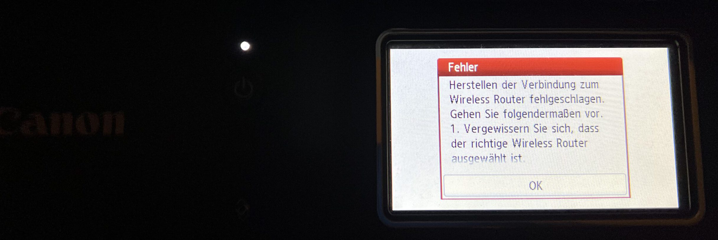
If your WLAN access point has activated WPA3 security along with the WPA2 standard, the Canon printer refuses to connect to the WLAN network and stops without asking for a password.
Canon did not help me very much: The interactive manual promises a solution that never comes. It offered a download page for software where I could not download anything. The name of the program that was supposed to fix the problem had changed – and guess what the software to fix the printer’s networking problem needs? Right – a network connection to the printer. USB does not work.
What had started this: I had to do some maintenance work in my home network; updating and resetting the OpenWRT firmware of my main WLAN router. And suddenly, the printer was gone. It refused any attempt at reconnection. It told me wireless encryption was off, but offered no option of reactivating it.
Strangely enough, I had the very same problem when trying to connect to my secondary AP, a Fritzbox managed by the ISP. So it couldn’t be the router update, then?
Well, yes, it could. I never noticed with the Fritzbox, but both routers now offer WPA3, a more modern and presumably better wireless security standard. (German Erklärartikel for AVM Fritzbox.) Which overwhelms the firmware of the four-year-old printer. Most recent update, of course.
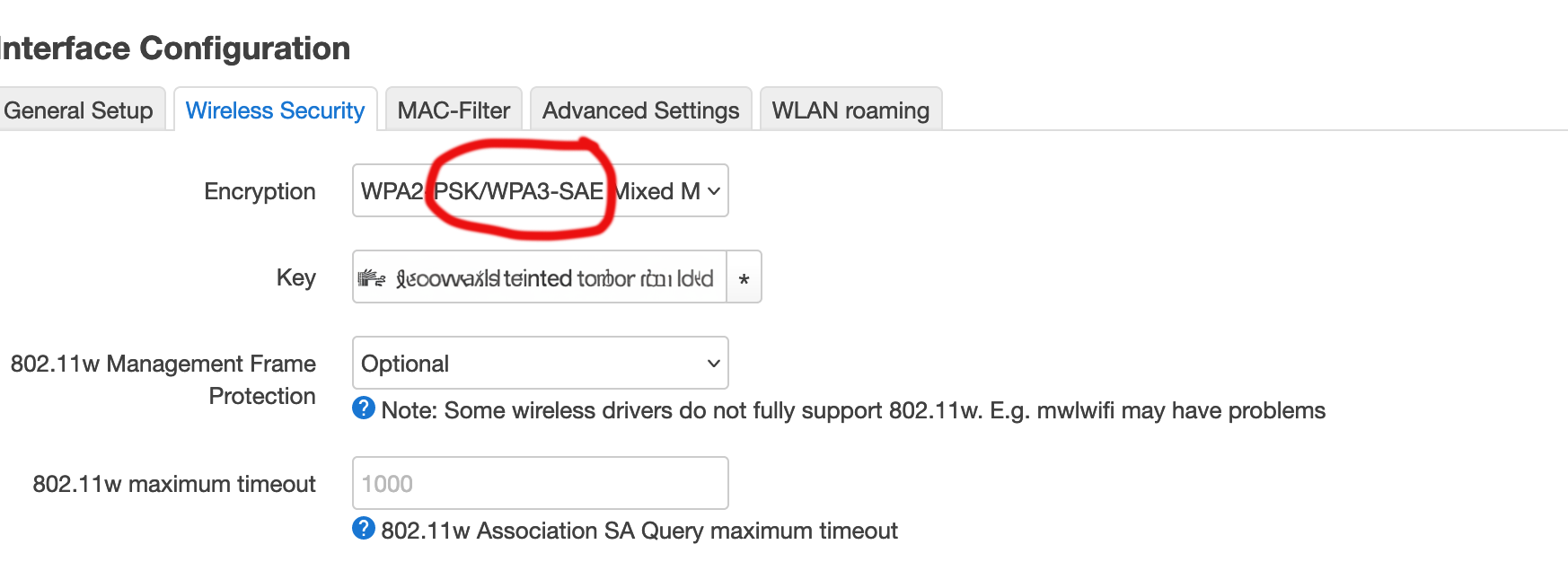
So what you will have to do is to limit wireless security. Meh. Like, maybe, a firmware update would be nice?
Honorable Mention: My Sony-Playstation 3 has been getting updates for over 15 years now, and continues to do so. Which is really, really rare in home electronics.
(I wasn’t willing to translate that myself; GPT-4 generated translation. German original here.)
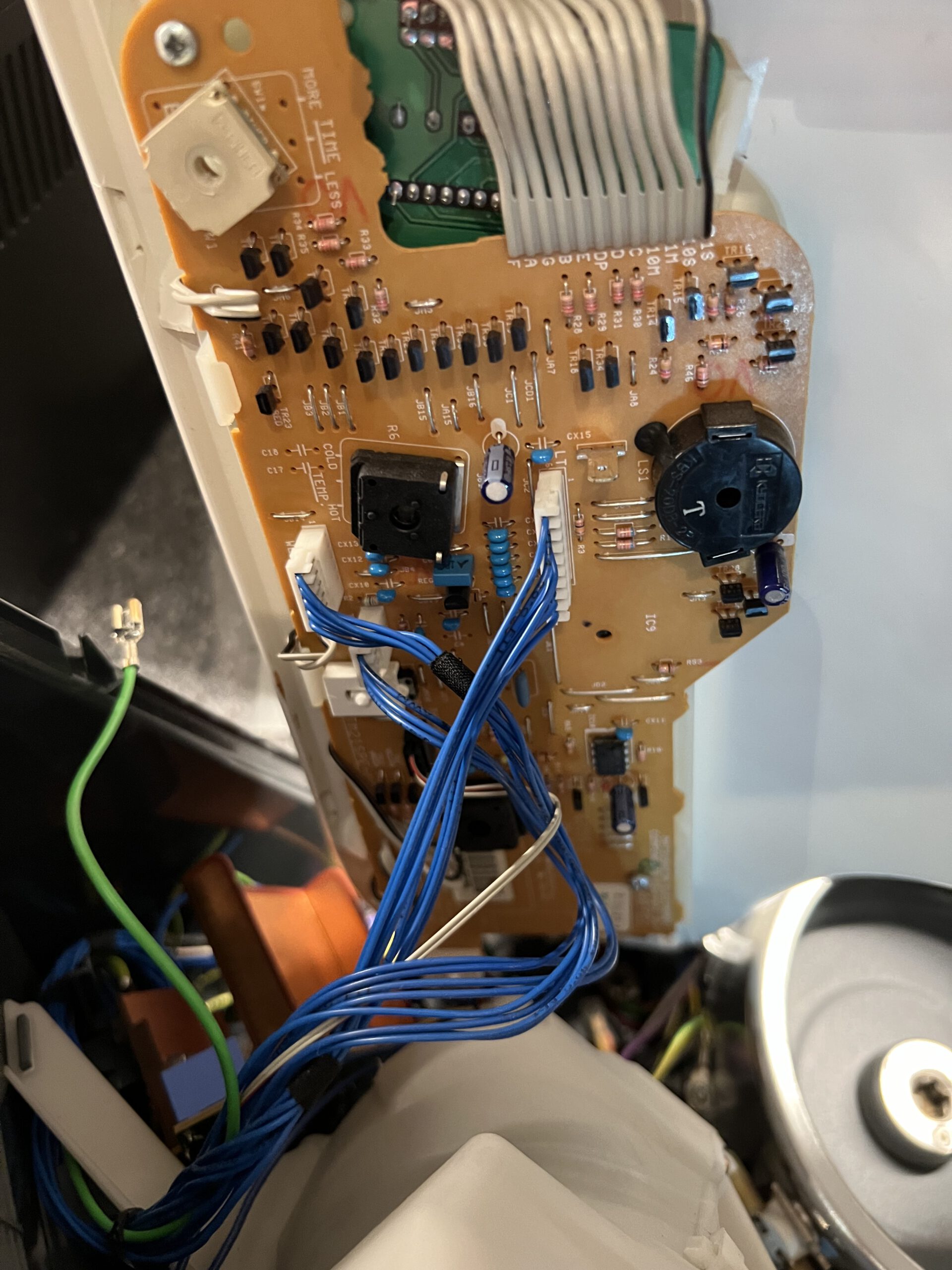
Blick unter die entfernte Oberschale; Kabel noch gesteckt
Unhooking and Folding Away the Upper Casing Shell
Next step is to unhook and fold away the upper casing shell. Disconnect the cables from the electronics – there are three white flat connectors with blue wires in different sizes, one black (with two grey cable cores), and the contact shoe of the green grounding wire. Once these are disconnected, you can remove the entire upper shell from the device.
Buggered those Push Buttons!
These can be tricky. That’s why it’s a good idea to watch a tutorial first.
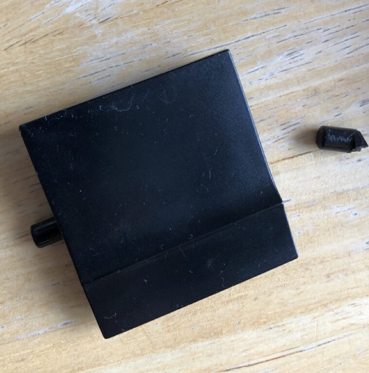
Understanding the Push Buttons Mechanism
The push buttons are comprised of two main parts: the actual button, which protrudes from the front of the casing with a pin attached to it, and a counterpart that keeps the switch contact closed as long as no one presses the button. To remove the button, you need to detach the top part from the pin. That much is clear.
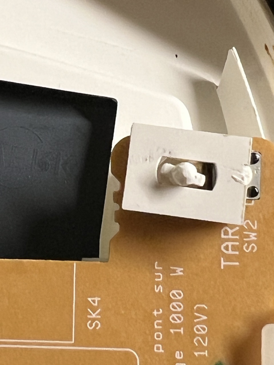
Unfortunately, the only solution I could think of was to use force, which led to me tearing off the rectangular plate on top. (This plate presses the switch.) It’s flanged to a tube where the pin goes, and at its upper end – visible through the slit below the plate – there are two small arms that hold the pin. You need to spread them apart using two small watchmaker’s screwdrivers, then you might be able to pull out the pin. Maybe.
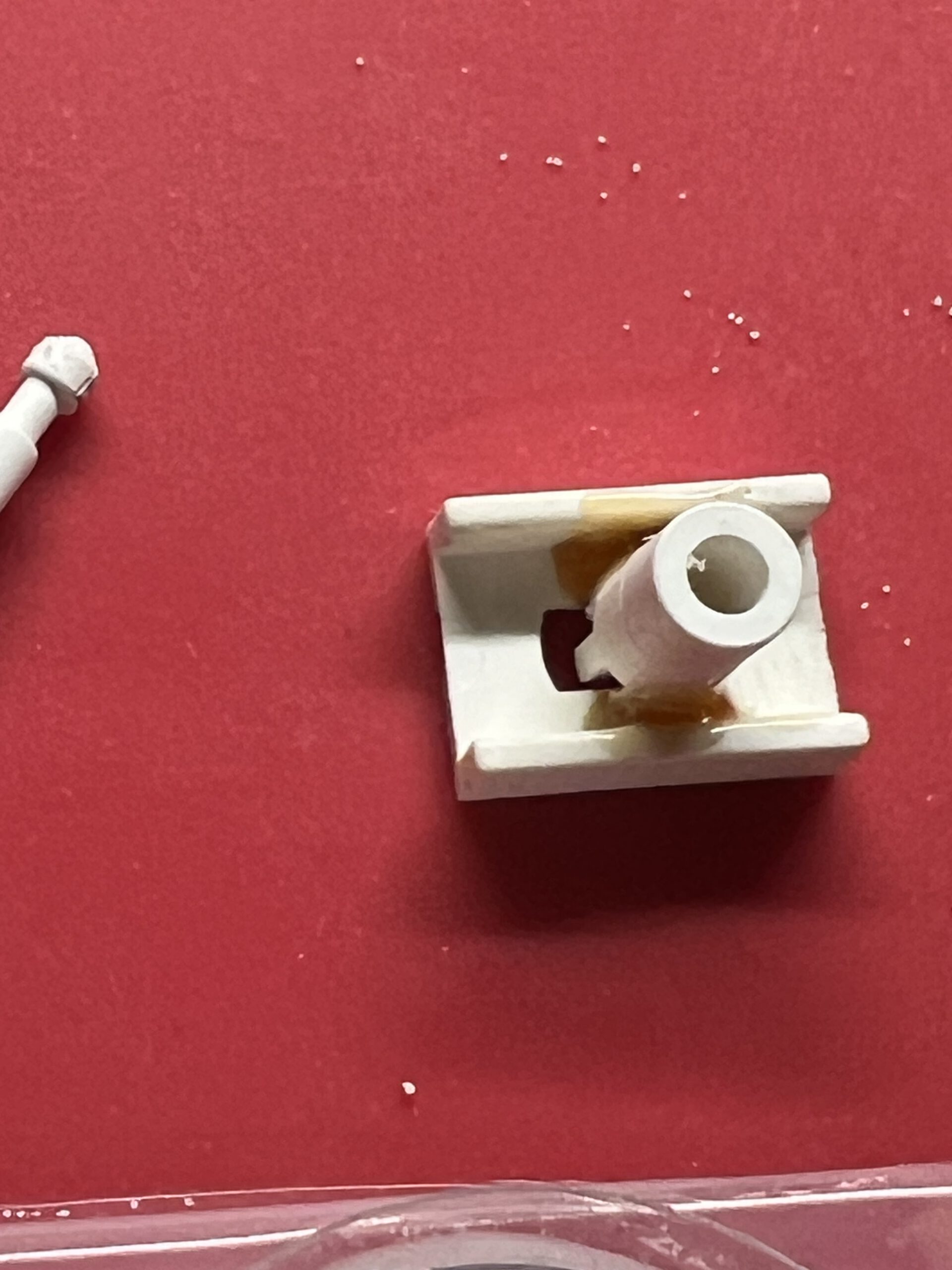
Or, it might end up looking like this – the part in the middle and the one on the right are actually supposed to be connected; I ended up brutally tearing them apart.
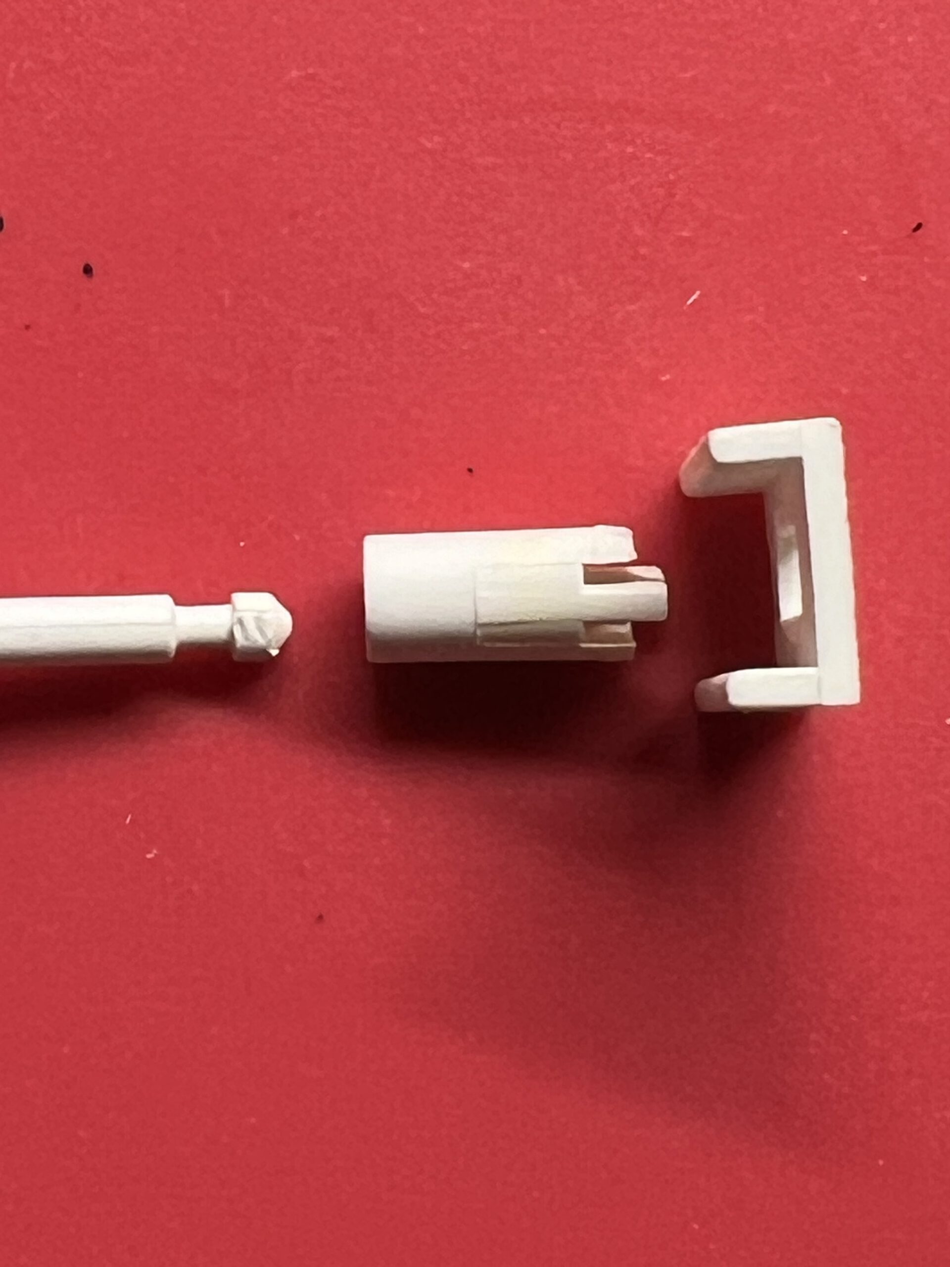
I resorted to the reliable two-component adhesive. It worked after reassembling, and I hope it holds permanently, though I’m not very confident. If I can’t find replacement parts, maybe I’ll 3D print them, or else I might just permanently attach the plate to the pin.
Next, unscrew the three screws from the circuit board and unhook the display, which is held in place by two plastic tabs. Then, remove the electronics.
The potentiometers are soldered at three contacts as usual and additionally held by two tabs that are inserted through the housing and bent over. Carefully unbend these, lift the three poles of the potentiometer, and remove it.
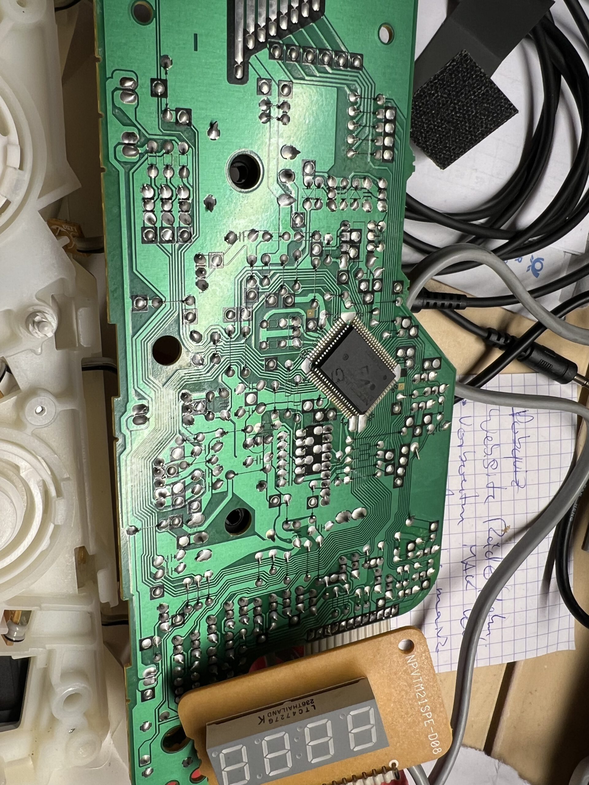
It’s a 22k potentiometer from Piher. I couldn’t find a replacement part quickly, so I decided to open it up. (Update: I’m trying with a Pipher PT15NH now; that’s the closest approximation I could find with that through-hole shaft. Piper datasheet here.)
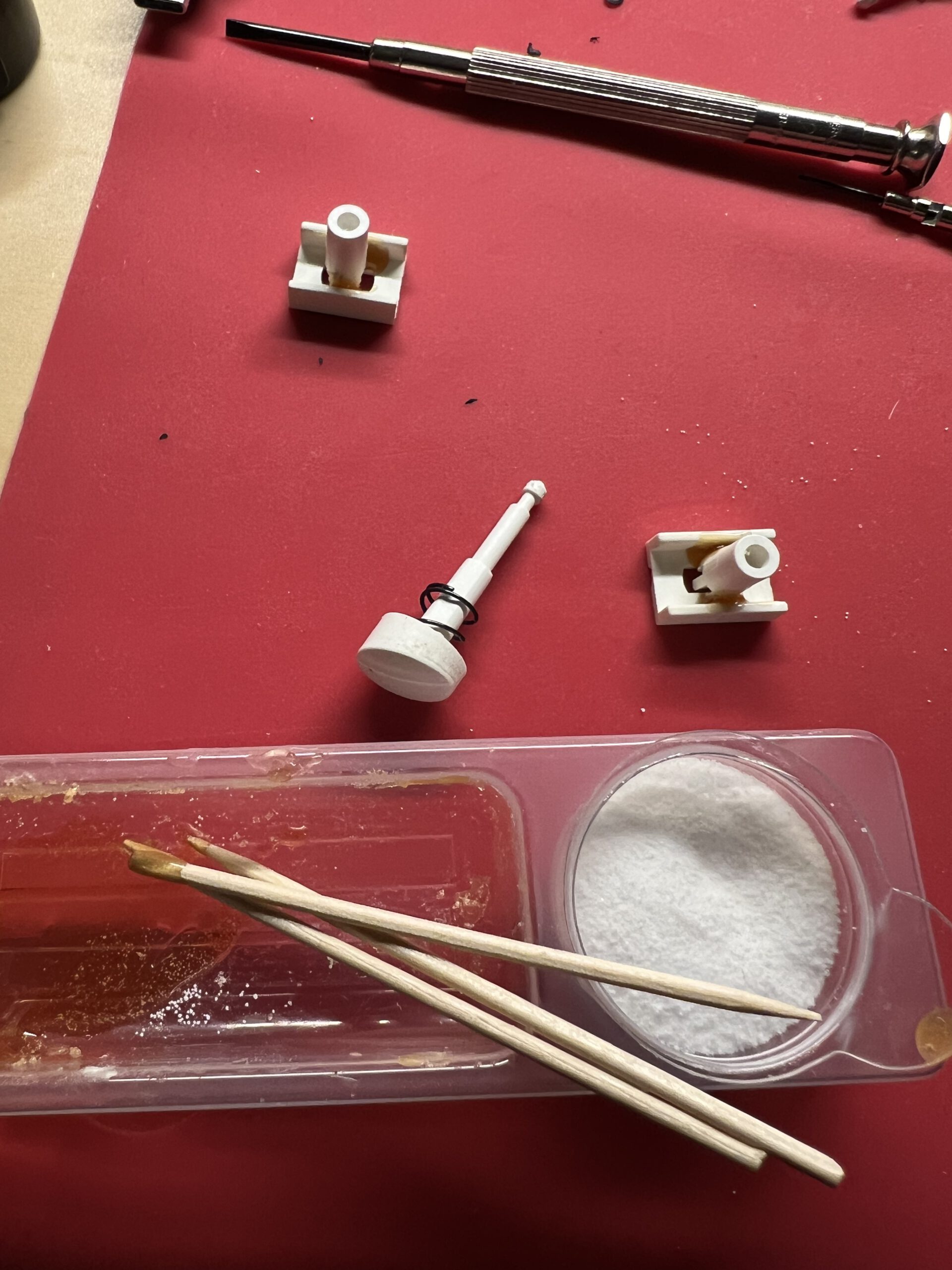
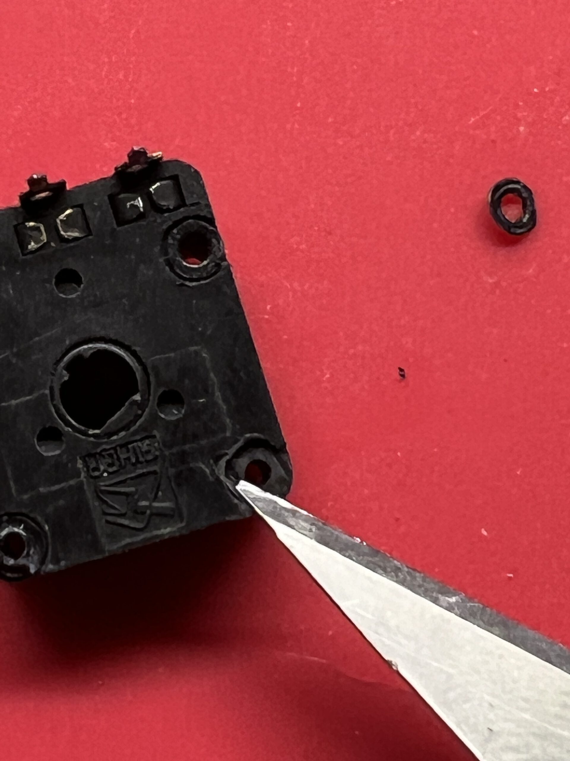
The cover is pressed onto the housing from the bottom and riveted over four plastic pins; you have to cut these slightly with a scalpel, then the cover can be pried open.
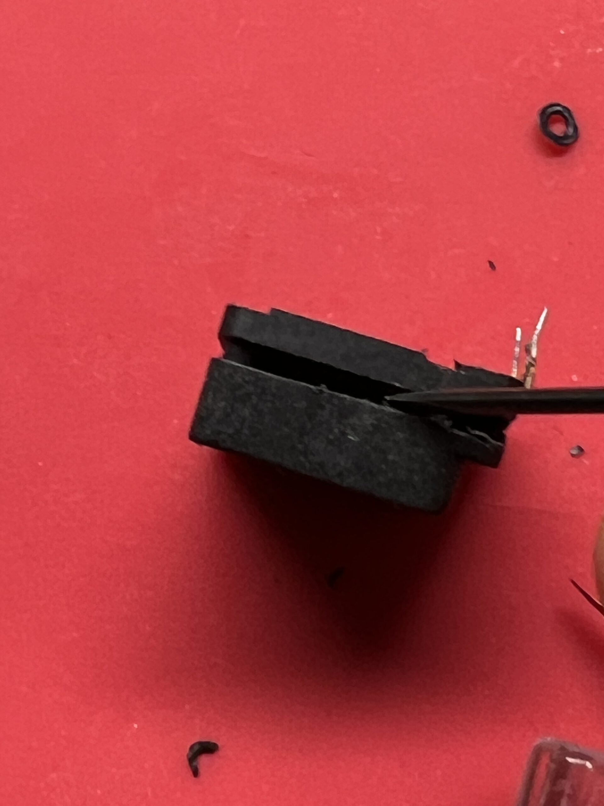
With the potentiometer open, do what one does with open potentiometers – clean the wiper and track with isopropanol or mild alcohol, gently bend the wiper contacts back into shape, and – I am grinding my teeth while writing this – apply a little contact oil, if available. Absorb any excess oil, reassemble the potentiometer, solder it back in place, bend the tabs back, and it’s done.
Reassemble everything – and it works.
…and don’t listen to the random guy on Youtbe.
This seems to happen quite often:
It is no problem to get a replacement holding clip, and it’s cheap. The larger problem is to fit the replacement part, as you will have to take the top part of the housing apart for that.
Continue reading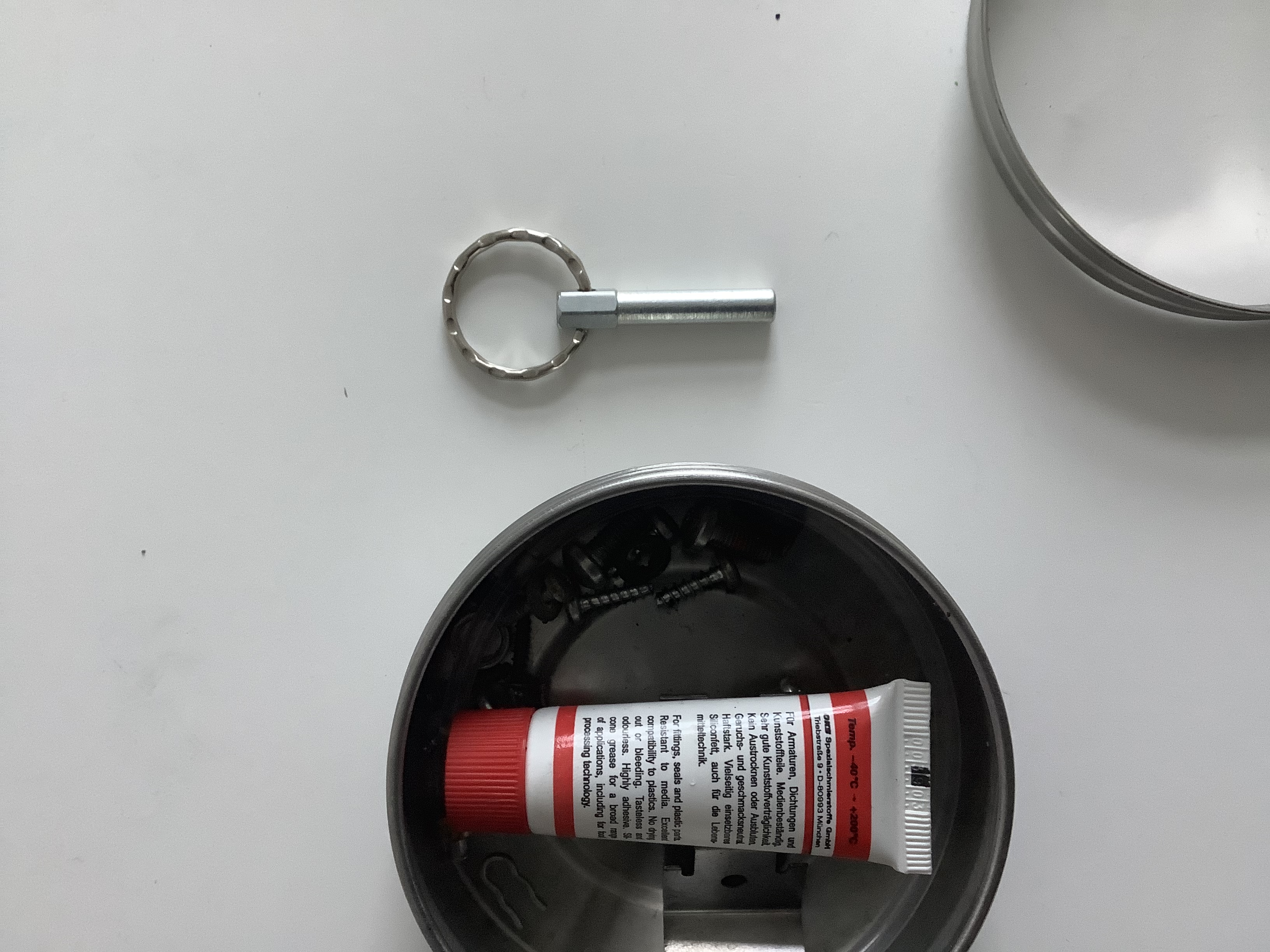
In which I am laying out the reasons for my conviction that the Jura brand coffee machine which I am trying to fix right now is a desaster. German only.
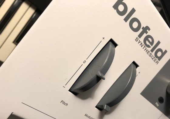
One day, my trusty Blofeld started drifting out of tune – pretty unusual behaviour for a digital synth. Even if it was in tune first, the drifting started as soon as I touched the pitchbend wheel, so I suspected that this was the culprit.
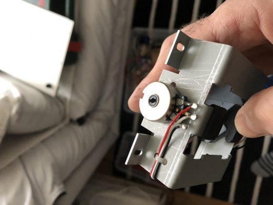
Opening the Blofeld (all 18 screws on the bottom – remember?), removing the wheelbox, and measuring the pitchbend pot confirmed that the potentiometer was indeed damaged – while an end-to-end-measurement showed 9k, the end-to-mid-resistance could be virtually anywhere, screaming “Mechanical Damage!” to me.
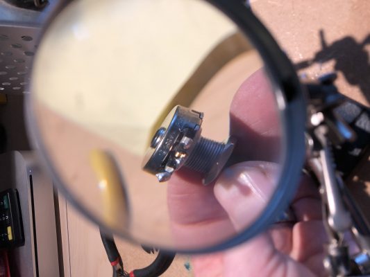
The potentiometer is 10k lin with a knurled 6.3mm shaft and an M10x0.75 mount. Waldorf seems to have used a Piher T-21Y type (datasheet). As I did not find something fitting in my parts boxes, I took it apart, cleaned it, adjusted the pickup spring, applied a bit of contact grease, refitted the pot and closed the Blofeld
Although I measured that the wheel now zeroed around the pot’s 5kOhm mark, it had most definitely shifted slightly, so I started looking for the calibration routine. There has to be a calibration routine, right?
But the good Blofeld seems to calibrate on power-up and on the first usage of the wheel – no calibration routine for the wheels needed. Phew!
Important note: Be careful to ensure that the Molex connector for the wheelbox sits correctly – when I pulled the plug, the plastic holder for the pins got pulled towards the edge of the PCB so when I reattached the plug, it did not sit correctly. Rule of thumb: If the plastic of the connector is visible from the top, you might want to push it back under the PCB.