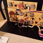
This knob is a good place to start: The “glide” potentiometer is in charge of portamento, and it is one of the first things that might make Jenny fail (see Neil Johnson’s site). A faulty glide pot means that the synth will only ever play the same note regardless of which key you press. So I did replace that pot, which is pretty straightforward – you’ll find some pictures in this gallery. (It is a 2.2M linear type BTW.)
The Glide pot is in the upper left corner of this picture. As you can see it is sitting on a small PCB together with the Noise switch and pot. Remove the knobs and the nuts from the axes of all three, and you can take out the board to replace the potentiometer.
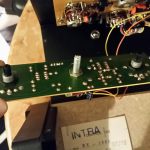
The pot needs to have a 10mm shaft and a 5mm diameter axis. Cut off the axis at about 10mm – which makes the distance from the end of the shaft to the top of the pot 20mm.
Pot soldered and screwed to the PCB. Ready to re-insert and re-attach the board into Jenny’s panel.
Overview of potentiometer values
This is an overview of the potentiometer values, some of them are linear, some logarithmic, a few antilog. The most obvious candidates for replacement, apart from the glide pot, would be Frequency (100k) and Resonance (100k) for the filter, and Tune (10k).
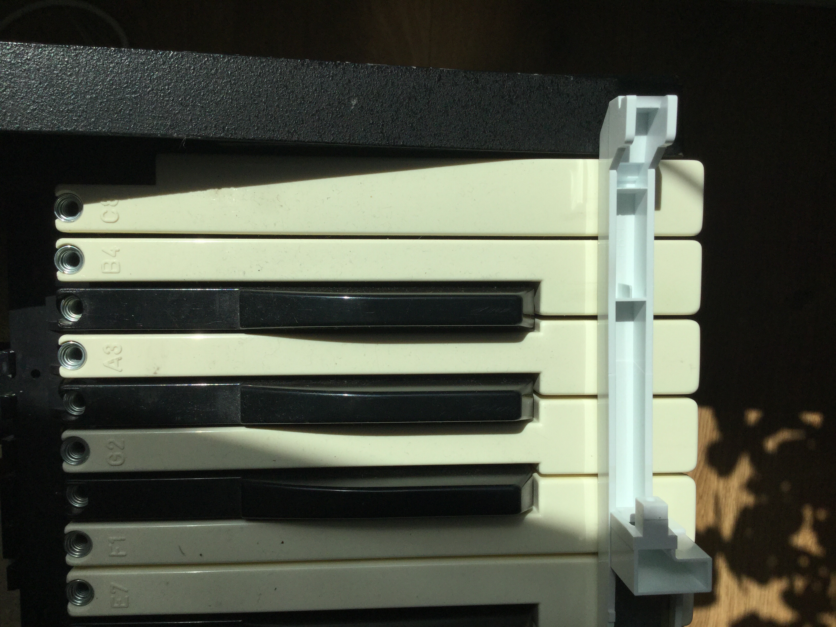
Jenny – my old 70s monosynth – is a beauty, and I love her knobby face. Her smile, though, has yellowed over the decades. So to make Jenny even more attractive, I decided to try and bleach the keys with hydrogen peroxide.
TL;DR: Effect has been minimal, so it’s probably not worth it. But it was fun. If you try it, make the Retrobright bleaching gel, don’t use a hydrogen peroxide bath. And have a good UV source.
Jenny’s keyboard compared to a key from a mid-80s Roland JX8P synth
Granted, there is already a Matrix editor panel, but it’s been in permanent Beta, and Chris’s panel simply looks great, from the layout of the controls, via the Matrix-movie branding, to the randomizer (brought up by clicking on the red pill, of course!). So: stay tuned!
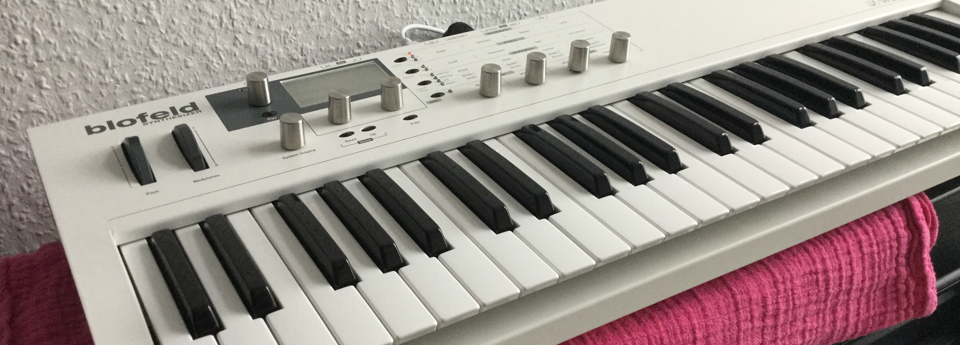
I like my white Blofeld. A very versatile VA synth with a good programming concept, and I am simply smitten with its look and feel. Solid metal, not too bulky or too heavy though, a big friendly graphics display, and a very good keyboard, with very good aftertouch sensibility. Got it really cheap, too.
As with the E-MU ESI32 that needed a new backlight, a steel casing means solid build quality – for the mechanical parts. BTW: To take it apart, you have to remove all the screws on the synth’s underbelly – 18 of them, casing screws as well as the ones holding the keyboard. No need to remove the wooden side panels or the rubber feet though. Then, remove all screws holding the electronics board – one of them is under the power switch so it is necessary to remove that switch from the housing by applying gentle pressure from the inside. In short, be warned: it’s a real pain in your lower backside to get the electronics dismounted, so if you do not have a good reason to remove Blofeld’s brain, just don’t.
Jumpy encoders being a very good reason, of course.
One thing that seems to plague the Blofeld, keyboard and desktop versions alike, is that the encoders are likely to behave eratically; they tend to become jumpy an unrealiable. Achim at stromeko.net, who has loads of insight into and experience with Waldorf synths and their tech, recommends soldering in buffer caps, but to make a long story short, I think you might be better off cleaning, lubricating, and bending rather than only soldering. I’d suggest addressing the mechanical problems first.
Jumpy? Greasy.
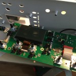
My Blofeld did indeed suffer misbehaving encoders. The two under the display were the worst, the ones that you use the most in tweaking sounds. This type of behaviour is not new to me; I fixed a Micro Q once, the Blofeld’s predecessor that had suffered from the same erratic encoder behaviour – after years of use. They still use the same kind of encoder – and these are easy to open and clean.
Once again, it proved that most problems in electronics are mechanical by nature – in my Blofeld, the encoders had been greased to ensure smooth operation, but a surplus of grease had seeped into the contacts. Update: Or so I thought – in fact it may be a special kind of grease to protect the contacts; you may use Kontakt-61 or a similar lubricant intended for contacts.
To fix the mechanical problems, carefully bend the pickup contacts on the rotor just the tinyiest bit higher to increase pressure After cleaning the encoder, and after re-applying the contact oil, encoder operation is now flawless.
To get to the encoders, the buttons have to be removed. Just pull them off.
The Blofeld’s brain – that’s all there is: one tiny chip does all the work.
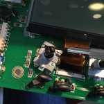
The encoder is held together by four metal tongues fixing the top part. Carefully wedge them away with a small flat screwdriver. Warning: the metal is easy to bend but will tear when bent repeatedly.
The top of the encoder, removed. This is the rotor. Clean carefully and, with even more care, readjust the feather contacts to compensate wear of older encoders.
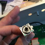
I am usually not too keen on chemical solvents like Kontakt spray, but it did good work as a degreaser here. Spray the solvent on a Q-tip rather than onto the encoder shaft – the grease is needed here.
A bit of degreaser applied to the base of the encoder. Clean and dry with a Q-tip, put the top part back, and bend the metal tongues back to hold it in place. Use a bit of force, or the encoder will tend to clatter.
The encoders are held together by four metal tongues from a very soft metal. It is very hard to bend it back into position so that it closes the encoder without play; a drop of hot glue holds the top in place and is easily removed if the encoder is due for maintenance again.
One final note: The main encoder left of the display is of a slightly different type where the metal tongues have to be straightened to pass through a hole in the top part of the housing. Extra care needed with that.
03-2020: Two important updates: There is a much simpler way to reset the memory in the Matrix – just hold the ENTER key while switching it on. You may have to repeat that a couple of times to get a stuck Matrix unstuck. And if you consider changing the battery yourself, you can find a step-by-step description with video here.
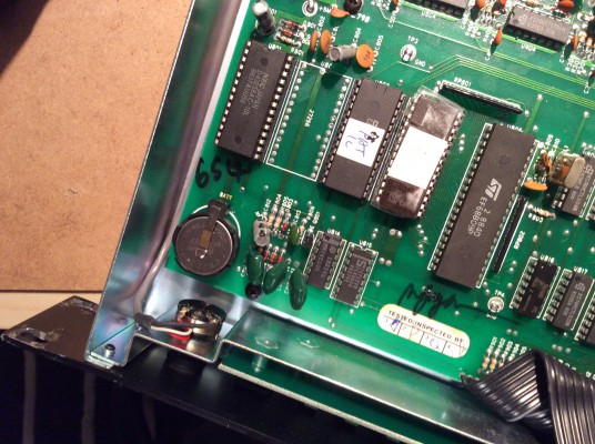
Well, to change the firmware, you have to open the Matrix and exchange the firmware EPROM for a new one, and doing that, I’ve noticed that this machine was still equipped with its original battery. By lucky chance, I am the proud owner of two Matrixes, and the battery in this one has been doing fine – what kind of super battery did they use in these days, has been in service ever since 1989, and still producing fine 3.0 Volts of power – but I decided to exchange it anyway for a new CR-2032.
As you might know, the battery in the Matrix-1000 is soldered in with most machines, as it was customary with most synths from these days. I guess they never thought that they were building for the anoraks of the future. No problem, I came across battery holders with the same 20.5mm raster used in the Matrix – so no need for drilling, just a simple solder-and-replace job. While soldering, I bridged the backup battery voltage with an external power supply, and I even thought of desoldering the GND terminal first – the rationale behind this being that soldering pens are earthed, so by soldering the positive terminal first you might short out the battery. (Actually bollocks, but I did it anyway.) So I saved my precious memory settings while soldering in the battery holder.
Only to slide in the new battery the wrong way round.
You might not have realised – well, I never do – but the pad connector of a CR2032 is actually the GND terminal, and the housing is Vcc. And is labeled with a clearly visible “+” sign. Well, I put the battery in the wrong way round anyway, thereby effectively losing all my patch and memory settings.
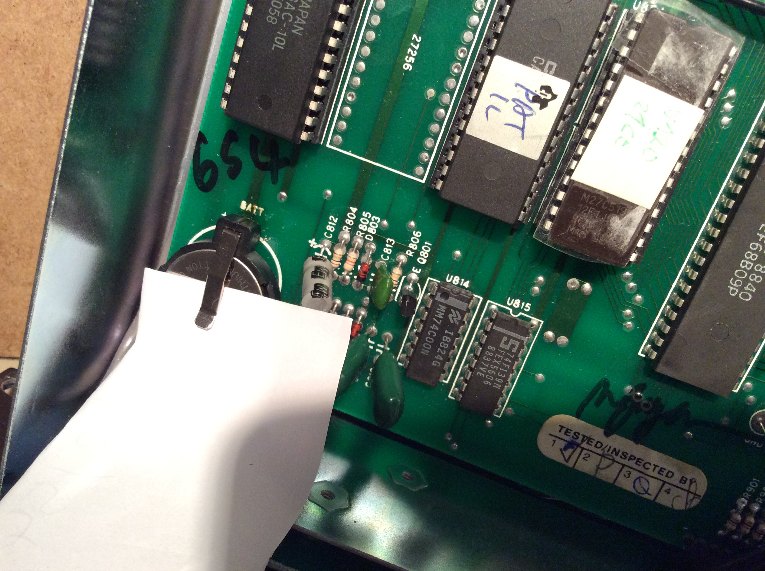
The battery in its new holder, now in the correct position: the plus terminal facing upwards
This is, of course, no big deal. I keep moving sound banks between my two Matrixes anyway, so I have pretty recent Sysex backups. Unfortunately, the unbuffered RAM chip lost just enough memory to put the machine into an undefined state – it would no longer boot beyond the init routine displaying the firmware version.
Switch off the the M-1000, disconnect it from mains, open it.
Disconnect the battery. Leave it disconnected.
Switch the M-1000 on, draining its buffer capacitors. Leave it for a couple of seconds – the completely powerless RAM should be all FF’s now.
Connect the M-1000 to mains, and switch it on. It should start now.
Do a calibration run, just to be sure. (Navigate to Ext. Funct., select 7, Enter, select 2, Enter.)
Reconnect the battery.
Done. Now you may switch off the Matrix, or supply it with fresh patch data.
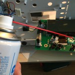
In case you may have wondered, there is a very simple and effective way to disconnect/reconnect the battery in a running machine: push a strip of paper between the battery and the battery holder’s terminal. Remove it to reconnect.
It enabled NPRN control of the Matrix’ parameters by removing a small bug
It sped up the VCF parameter control by skipping seemingly unnecessary calculations
It told the synth to discard all parameter edits except the most recent one, thereby keeping the synth responsive.
This is a huge improvement and makes the Matrix feel and behave almost like a modern instrument. But it gets even better.
Matrix-6 project, Matrix-1000 upgrade
Bob Grieb has been analyzing the Matrix-6/1000 code for months. I guess you can say that these days, not even Marcus Ryle does understand the code as well as Bob does. Here is his explanation why the Matrix-6/1000 machines are not real-time responsive to parameter changes in the first place – it is the downside for the immense amont of real-time modulations the Matrix is capable of – 22 fixed modulation paths, 10 matrix modulation slots, 3 envelopes, 2 LFOs and 2 ramps. To implement that in software the programmers used a special technique; a pre-calculated memory area for each voice called the voice update stack. Quote:
This stack contains pointers to code, ptrs to variables, and some pre-computed values. Only pointers to the code needed to handle the enabled features are placed on the stack… This is a very fast and efficient way to update the voice cv’s.
A downside of this approach is that when parameters change, the stacks need to be updated for all six voices. Some parameter changes just affect one number on the stack, so that number can simply be changed very quickly. But some parameters can change the size of the stack. This is a problem, as the update values for that parameter may be in the middle of the stack.
This means moving around chunks of memory to make room for the updated parameters, and it has to be done for all six voices, which takes the ancient 8-bit, 2-MHz CPU a couple of milliseconds. When you turn an external VCF controller, all these parameter changes add up, and the machine freezes for a long, terrible moment, until it catches up. (Read Bob’s full description of the issue here.)
GliGli’s main trick is to tell the machine to discard anything but the last Sysex command. He also noticed that sometimes the stack is rebuilt although this is not technically necessary. And this is the road that Bob has been following. He rewrote parts of the firmware to handle a set of about a third of the parameters much, much faster – including VCF frequency and resonance, DCO PW and LFO control, and VCA level. Changing these parameters with an external controller will be smoother than with older firmware, others – increasing the effect of a modulator in the mod matrix – will still cause the machine to glitch.
Update, 2016: Now that you’ve made it this far, you’ll be glad to learn that Bob made his revised code available for Matrix-1000s and Matrix 6/Rs. You can get a firmware EPROM from him or, if you are in Europe, from me – just follow the links above.
This was originally a project for the Matrix-6, but Bob ported it over to the Matrix-1000. In the process, he also redrew the schematics, so that after all these years, there is finally a legible circuit diagram for the M-1000 on the net. Incidentally, it prompted another guy to scan his printed schematic and send it to Bob, so that there are now not only one usable version but two. (Download link to ZIP archive here.)
No, that Bass Station you are trying to play isn’t dead. It’s just gone… to an undefined state.
I had a Novation Bass Station that did not produce a single sound. Although I could confirm that MIDI was still working – the device was sending Key ON/OFF and CC messages – and the LFO LED was blinking and responded to parameter changes, the synth was mute. And some research on Ebay and on the net confirmed that there are lots of Bass Station owners with the very same problem. Continue reading →
Pretty straightforward, this one: Replace the JEN SX-1000‘s fixed power cable with an IEC socket. (Like weird German words? You’ll love this: In German, this thing is called a “Kaltgerätestecker”, more precisely, a “Kaltgeräte-Steckverbinderbuchse”, which translates to “Cold unit connector socket”. Don’t ask me.)
No problems here apart from cutting a hole for the socket; I used steel drills to mark the corners of the cutout and then cut the steel with my Dremel tool. Lots of metal dust but fast, and it did the job precisely.
A word on Jenny’s power supply: It’s extremely oldschool – a transformer and a diode bridge generating +/-18VDC, two 7812 regulators generating +12V and -12V, and another 7805 regulator generating the +5V supply rail from the 12V. If you would like your JEN to be a bit more eco-friendly I’d advise replacing those regulators by the 2931CT low-dropout type, but apart from that, there’s hardly any reason to look at the power supply – it’s rather solid and possibly not your primary concern if the synth does not work.
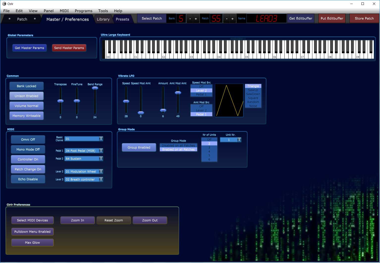
If you have found this blog searching for the Oberheim Matrix-6/1000 synthesizer, you may already know that I still haven’t given up on breathing new life into hardware and software of this wonderful machine, and that I have made a controller template for the iPad. A controller, mind you, not a true editor – but a tool to control each parameter in a sound preset via a dedicated touch control, and pretty much without alternative.
No longer – there is a true Matrix editor app in the Store now, Patch Touch by Coffeeshopped, LLC. How does it compare? Is it worth the 15 30 Dollars or Euros? Chadwick, the guy behind Coffeeshopped, was so kind as to send me a download code for his app, and to comment on an early draft of my observations, so you’ll find my remarks updated with his comments here. Continue reading →
Is it possible to retrofit an Alesis IO Dock II with an internal USB hub, just like I did with my IO Dock 1? TL;DR: Some have tried and failed – seems like Alesis deliberately switched the code for this hack off.
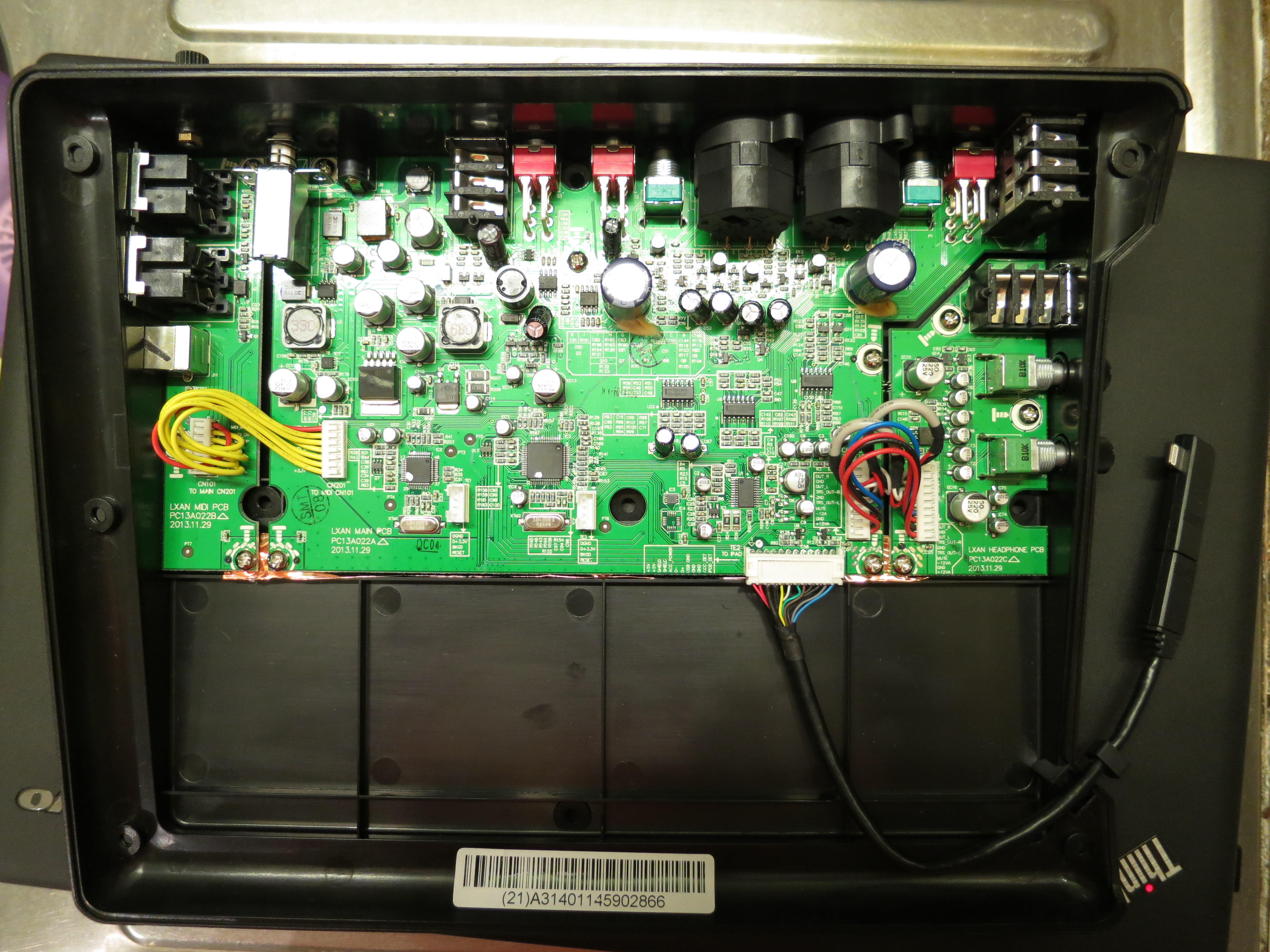
This photo was sent to me by Blek in the Czech Republic who asked that very same question. He has taken a look inside his IO Dock II and noted that it features an all-new PCB, so my original hack won’t work. And of course there is no guarantee that the prerequisite for the original hack is still implemented in the IO Dock II: the ability to function not only as a USB bus host for the iPad, but as a USB bus slave device, with the iPad working as the bus master.
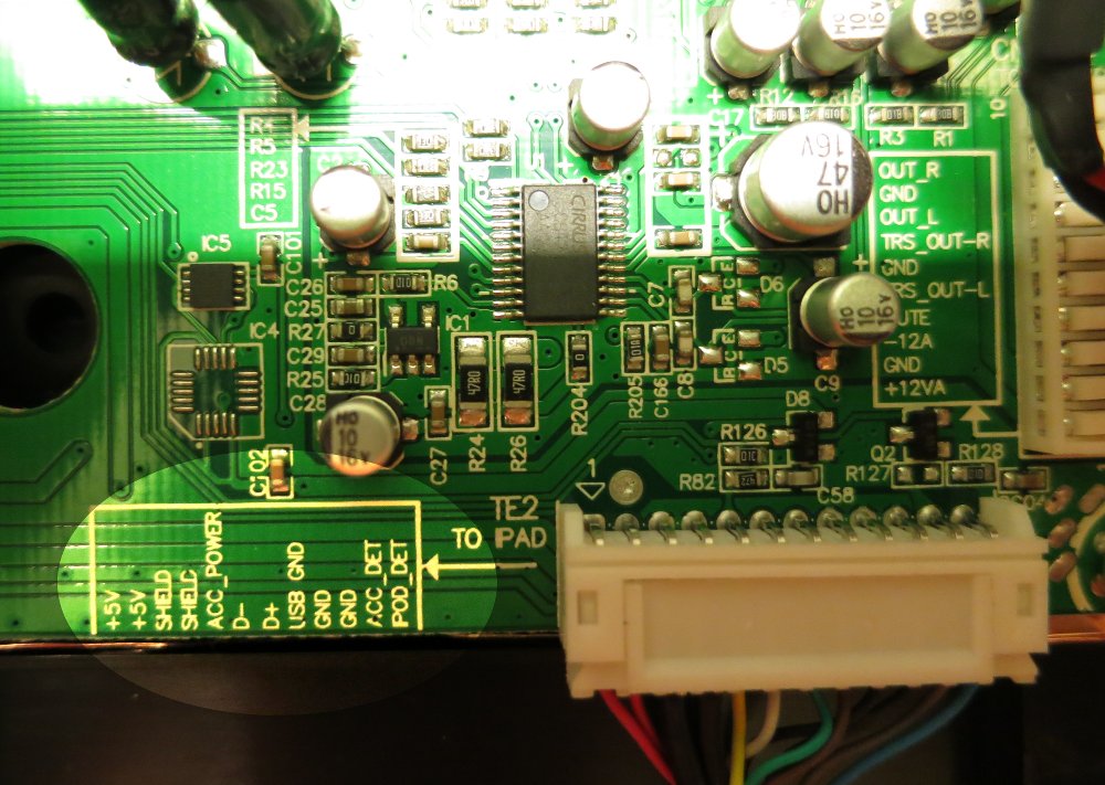
The good news is: It is simple to give it a go, as Alesis took extra care to label the locations of the USB bus signals:
So here is what you do to try it:
Get a male-female pair of plugs matching the connector in question. Possibly a 12-pin version of these connectors, so as in the original hack, 2mm pin grid stripes could work. They are a bit hard to come by, but it is possible.
Solder connections from male to female for all lines but 6 and 7 – the D- and D+ USB data signals.
Get a suitable UBS2.0 hub – I used a Belkin F5U404; you might have to try a couple of hubs if that one does not work.
Take the cable that is meant to connect the hub to the computer – it should have a standard USB plug on one end and a USB mini connector on the other end – and cut it in half. This is the only non-reversible action you are taking, but as it is easy to buy a replacement cable, there is not much harm done if it does not work.
Take the cable half with the USB A-type plug, for connecting it with the computer. Solder the cable wires to the connector that goes into the IO Dock side as follows: Red (Vcc) -> pin 1, White (D-) -> pin 6, Green (D+) -> pin 7, Black (GND) -> pin 8.
Take the other cable half with the USB mini-B plug for connecting to the hub and solder it to the iPad side, i.e. to the connector that is leading to the iPad connection cable. Once again, solder red to 1, white to 6, green to 7, and black to 8.
Do some checking for connections and possible short-circuits. Believe me, it’s worth the effort.
Unplug the IO Dock board connector for the iPad. Insert your freshly-made adapter.
If it works, make a video of it. Become world famous. :)
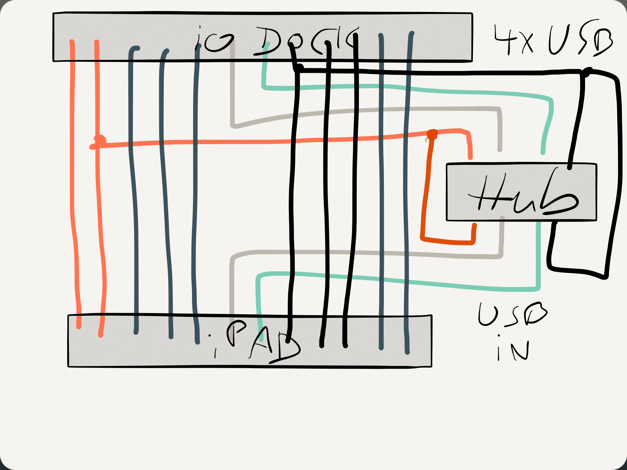
Wiring the USB hub connector: Once again, the trick is having the iPad work as USB host rather than as a slave device, and the IO Dock as the slave rather than as the host. Use your hub’s connector cable, cut in half, and solder the color-coded wires to the connectors as shown.
Sorry for my rather artistic impression of the adapter, hope it gives you the right idea. Pin 1 is to the left, pin 12 to the right. IO Dock side is up, iPad connector side is down.
Just to be sure:
I’d strongly advise you to solder and try out the adapter rather than soldering any wires to your IO Dock. It is a good thing to keep that sort of stuff reversible. For this reason, don’t start dremeling before proving that it actually works…
…which I won’t guarantee you. Mind you, I don’t even own an IO Dock any more. If you start doing this, you should know what you are doing.
Please understand that the base for this hack is a feature that Alesis seems to have implemented deliberately into the first IO Dock (see Dan Radin’s comment): the ability to work as a USB slave to the iPad, in addition to normal operation, where the IO Dock works as a host for the iPad. If the IO Dock does no longer do that, you can try to rotate the USB hub, but that’s about it.
Please write me back with your experiences. Please don’t get on my tits with any attempts to make me do this hack for you, or repair your IO Dock if anything went wrong. (Oh my god – I just realize that bullshit warnings are obviously contagious.)
It’s worth giving it a try, isn’t it?
Thanks to Blek for allowing me to use his pictures.
This website uses cookies to improve your experience. We'll assume you're ok with this, but you can opt-out if you wish.AcceptRead More
Privacy & Cookies Policy
Privacy Overview
This website uses cookies to improve your experience while you navigate through the website. Out of these, the cookies that are categorized as necessary are stored on your browser as they are essential for the working of basic functionalities of the website. We also use third-party cookies that help us analyze and understand how you use this website. These cookies will be stored in your browser only with your consent. You also have the option to opt-out of these cookies. But opting out of some of these cookies may affect your browsing experience.
Necessary cookies are absolutely essential for the website to function properly. This category only includes cookies that ensures basic functionalities and security features of the website. These cookies do not store any personal information.
Any cookies that may not be particularly necessary for the website to function and is used specifically to collect user personal data via analytics, ads, other embedded contents are termed as non-necessary cookies. It is mandatory to procure user consent prior to running these cookies on your website.