Is it possible to retrofit an Alesis IO Dock II with an internal USB hub, just like I did with my IO Dock 1? TL;DR: Some have tried and failed – seems like Alesis deliberately switched the code for this hack off.
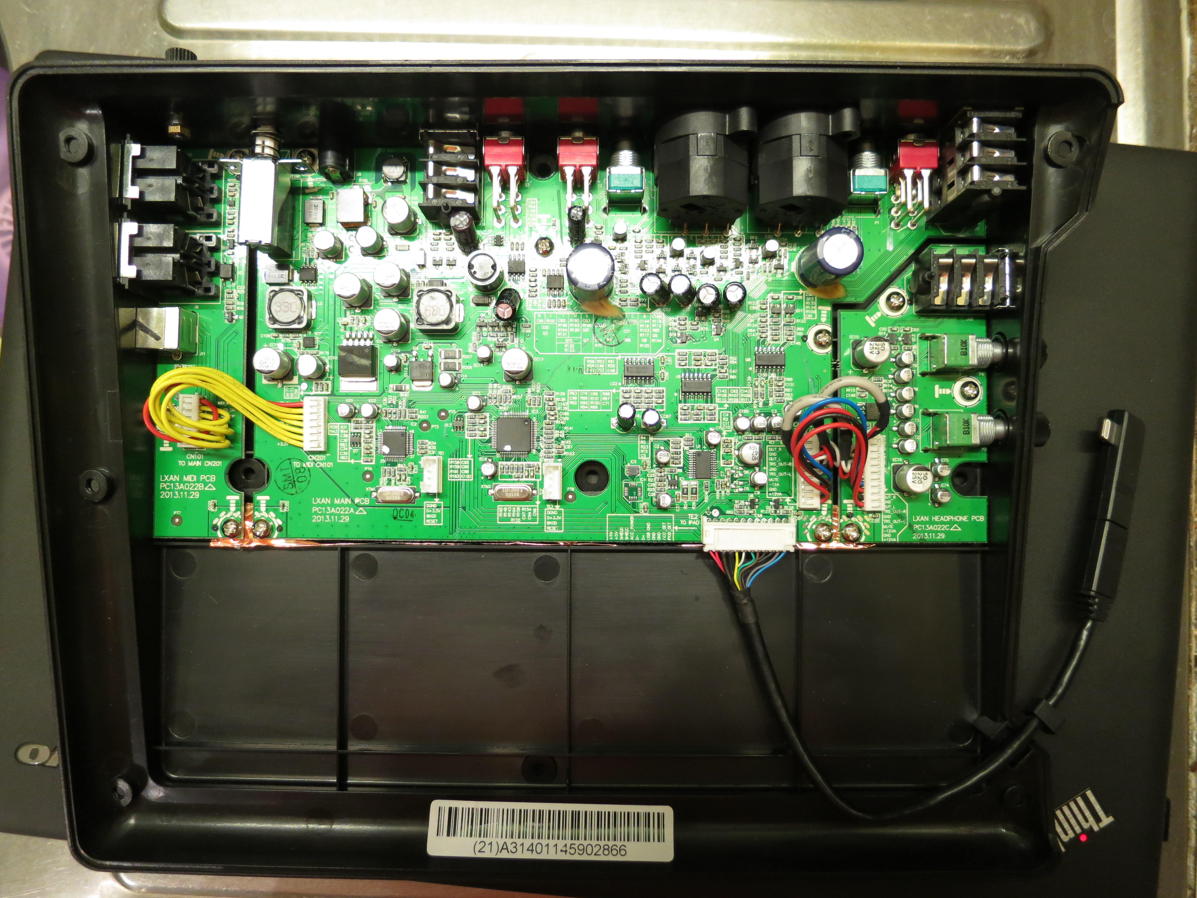
This photo was sent to me by Blek in the Czech Republic who asked that very same question. He has taken a look inside his IO Dock II and noted that it features an all-new PCB, so my original hack won’t work. And of course there is no guarantee that the prerequisite for the original hack is still implemented in the IO Dock II: the ability to function not only as a USB bus host for the iPad, but as a USB bus slave device, with the iPad working as the bus master.
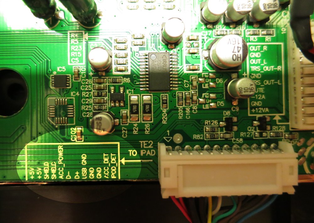
The good news is: It is simple to give it a go, as Alesis took extra care to label the locations of the USB bus signals:
So here is what you do to try it:
- Get a male-female pair of plugs matching the connector in question. Possibly a 12-pin version of these connectors, so as in the original hack, 2mm pin grid stripes could work. They are a bit hard to come by, but it is possible.
- Solder connections from male to female for all lines but 6 and 7 – the D- and D+ USB data signals.
- Get a suitable UBS2.0 hub – I used a Belkin F5U404; you might have to try a couple of hubs if that one does not work.
- Take the cable that is meant to connect the hub to the computer – it should have a standard USB plug on one end and a USB mini connector on the other end – and cut it in half. This is the only non-reversible action you are taking, but as it is easy to buy a replacement cable, there is not much harm done if it does not work.
- Take the cable half with the USB A-type plug, for connecting it with the computer. Solder the cable wires to the connector that goes into the IO Dock side as follows: Red (Vcc) -> pin 1, White (D-) -> pin 6, Green (D+) -> pin 7, Black (GND) -> pin 8.
- Take the other cable half with the USB mini-B plug for connecting to the hub and solder it to the iPad side, i.e. to the connector that is leading to the iPad connection cable. Once again, solder red to 1, white to 6, green to 7, and black to 8.
- Do some checking for connections and possible short-circuits. Believe me, it’s worth the effort.
- Unplug the IO Dock board connector for the iPad. Insert your freshly-made adapter.
- If it works, make a video of it. Become world famous. :)
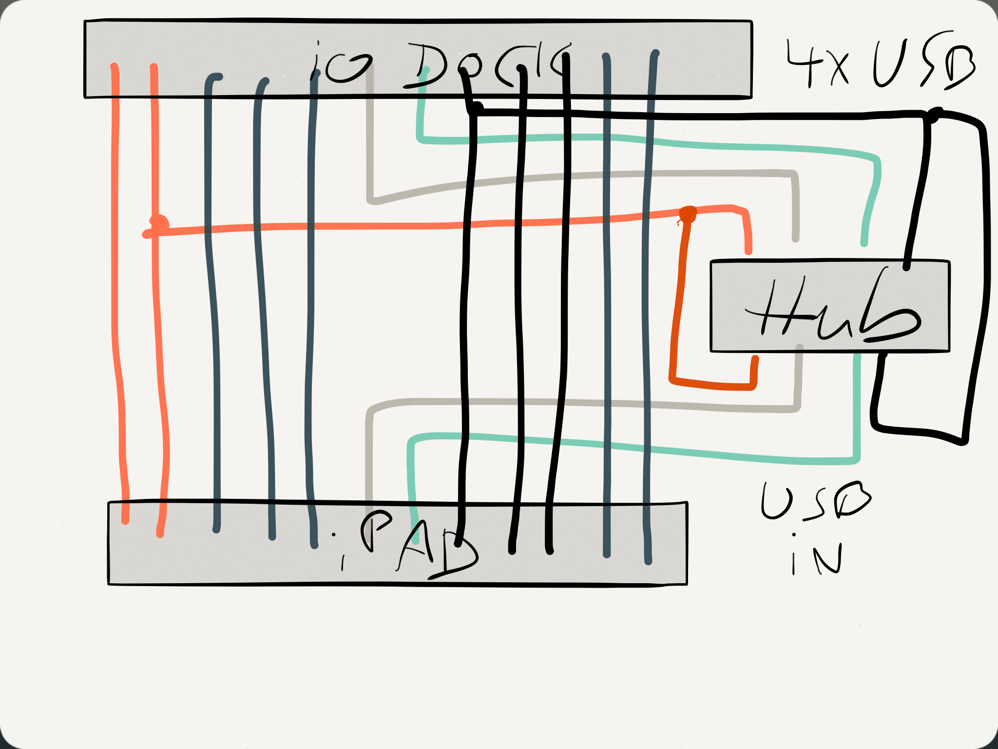
Wiring the USB hub connector: Once again, the trick is having the iPad work as USB host rather than as a slave device, and the IO Dock as the slave rather than as the host. Use your hub’s connector cable, cut in half, and solder the color-coded wires to the connectors as shown.
Just to be sure:
- I’d strongly advise you to solder and try out the adapter rather than soldering any wires to your IO Dock. It is a good thing to keep that sort of stuff reversible. For this reason, don’t start dremeling before proving that it actually works…
- …which I won’t guarantee you. Mind you, I don’t even own an IO Dock any more. If you start doing this, you should know what you are doing.
- Please understand that the base for this hack is a feature that Alesis seems to have implemented deliberately into the first IO Dock (see Dan Radin’s comment): the ability to work as a USB slave to the iPad, in addition to normal operation, where the IO Dock works as a host for the iPad. If the IO Dock does no longer do that, you can try to rotate the USB hub, but that’s about it.
- Please write me back with your experiences. Please don’t get on my tits with any attempts to make me do this hack for you, or repair your IO Dock if anything went wrong. (Oh my god – I just realize that bullshit warnings are obviously contagious.)
It’s worth giving it a try, isn’t it?
Thanks to Blek for allowing me to use his pictures.