Let’s start with some good news: Jenny‘s here to stay with me, so I can start some serious modding. The single VCO and the filter design make it hard for her to growl credibly, so I tried to make her bark and her bite a bit tougher, using bits and gates from my basement supplies: adding a sub-oscillator, and pre-filter overdrive.
Subjenny
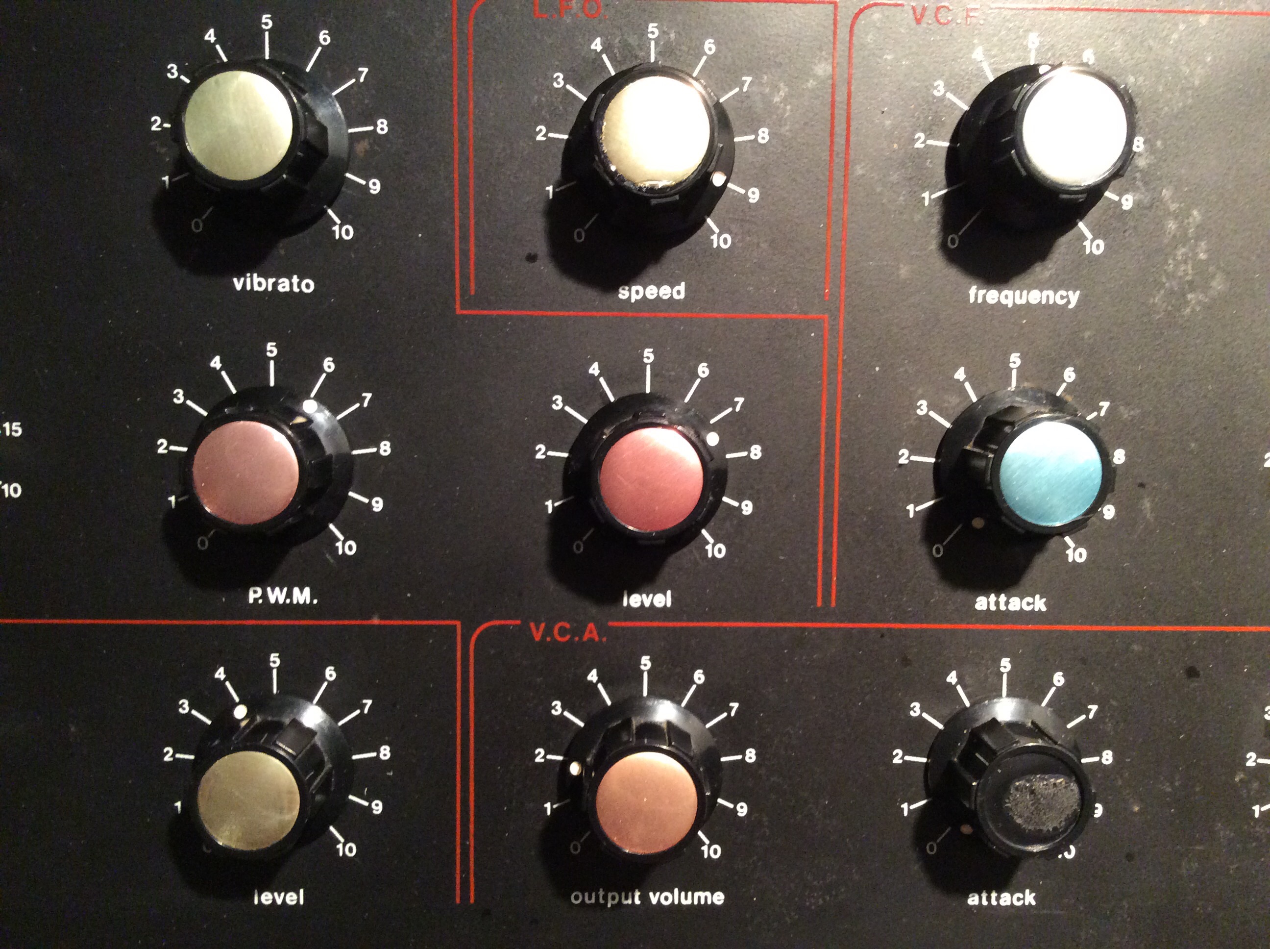
The sub-oscillator is simple and has been done by many great modders: You add a divider circuit to produce a one-octave (or two-octave) square-wave sub-oscillator and feed the signal to the unused “Off” terminal of the noise selector switch (over a 100k resistor so that the sub-osc signal is not overly loud). So now when the noise generators are switched off you can use the noise dial to add some deepness.
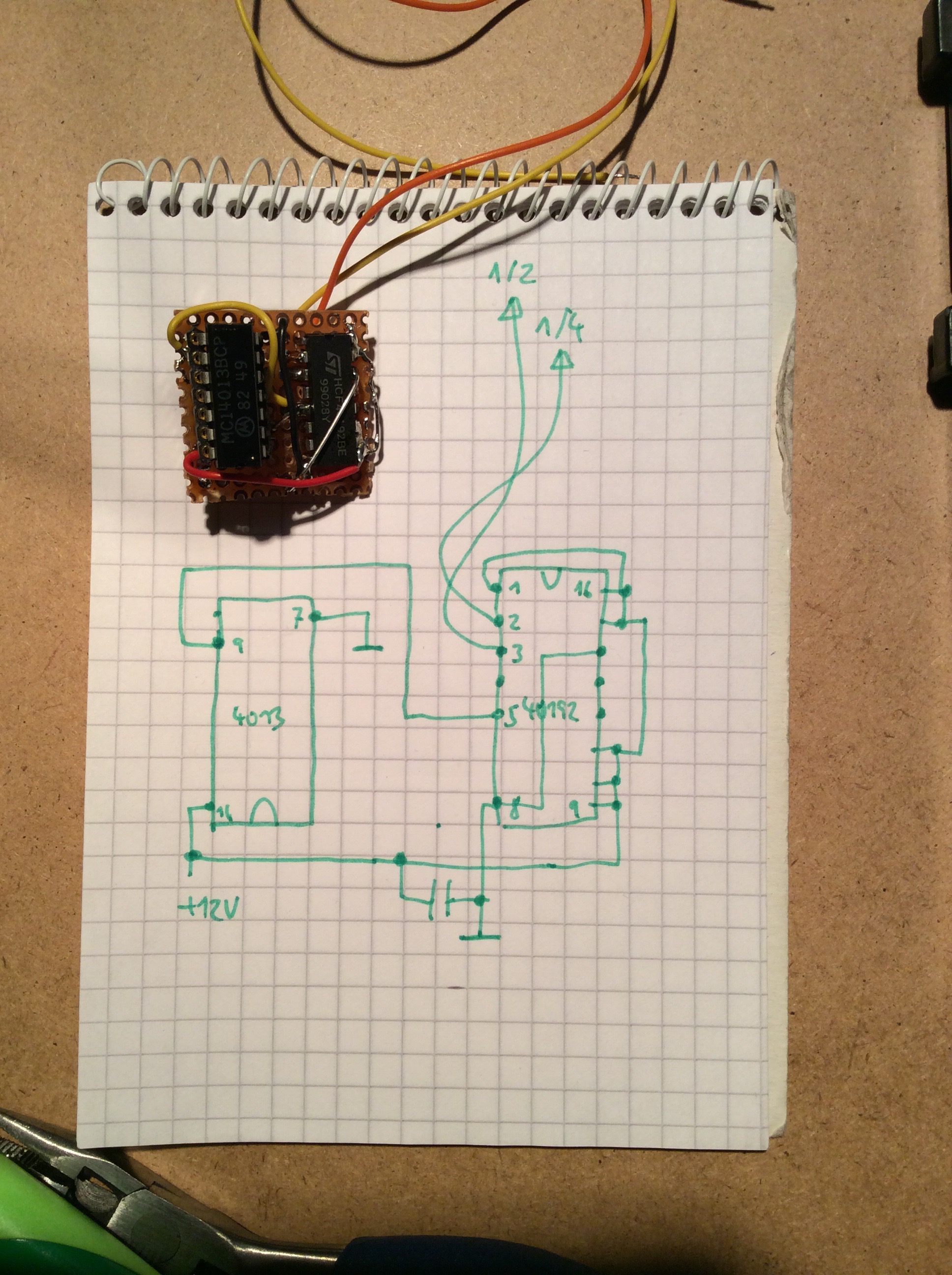 Nothing difficult in here, the only complication being that I did not have any 4013 dual D-type flip-flops that everybody except Neil uses as frequency-divide-by-two circuitry. I came to use something a bit more esoteric: a 40192 BCD(!) programmable up-down counter, because these were the only suitable CMOS frequency dividers I had on stock. I also did not want to solder anything to the original JEN IC’s, so I designed a small piggyback board to go between the 4013 on the oscillator board and its socket. It diverts the supply voltage and the square oscillation to the 40192. I also found that you’ll have to reduce the signal a bit if you do not want it to drown out the main osc; a 100k resistor in the path means -6dB if I’m not mistaken.
Last modification of the modification: I had a four-position rotary switch to replace the standard 3-position switch for noise selection. Old maker’s words: If you have it, use it.
So I tried out some rather unusual sub-oscillator sonics.
Ask not what a frequency divider can do for you…
As mentioned before, my sub-osc is built as a piggy-back replacement for the 4013 on the VCO board.
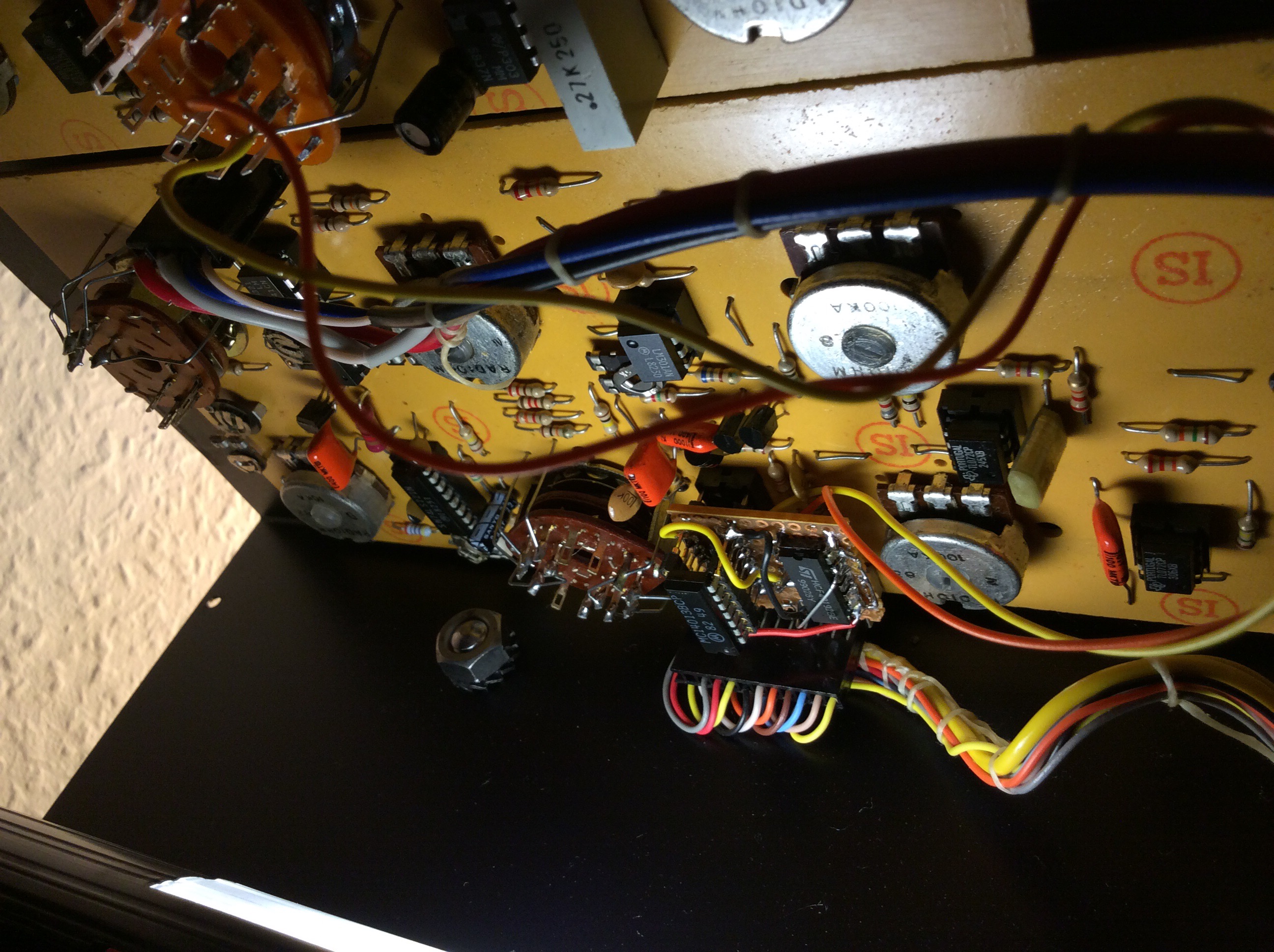
My first attempt hat the 4013 the wrong way round, so the add-on PCB is not remotely as pretty as it could be. Anyway, it works. Here’s a comparison of the Jen’s original sawtooth wave, and a sawtooth wave played one octave higher with some sub-osc added.
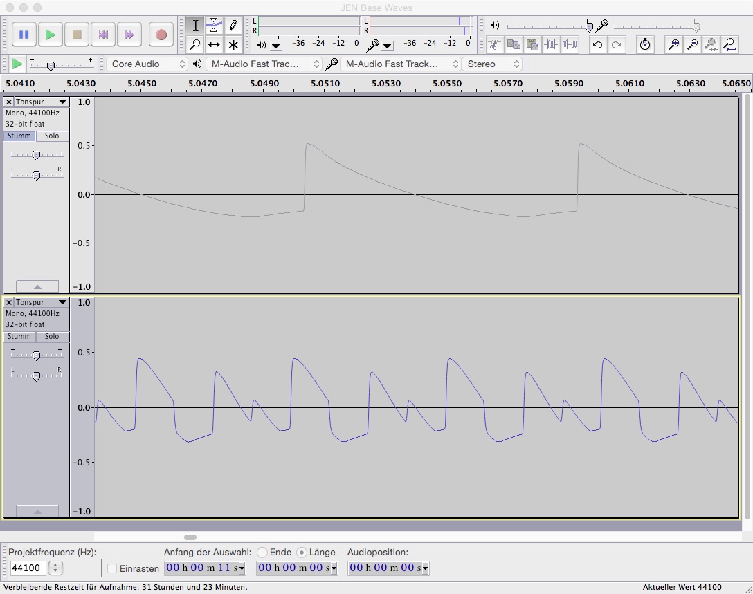
I also switched some resistors on the noise board following Ken’s level adjustment advice to raise the noise signal levels a bit (see his PDF) but found that the new sub-osc signals were too loud. So I added the 100k resistor in the path as mentioned above; it becomes of the voltage divider via the noise level pot and effectively halves the signal level (i.e. -6db).
The madness of 40192
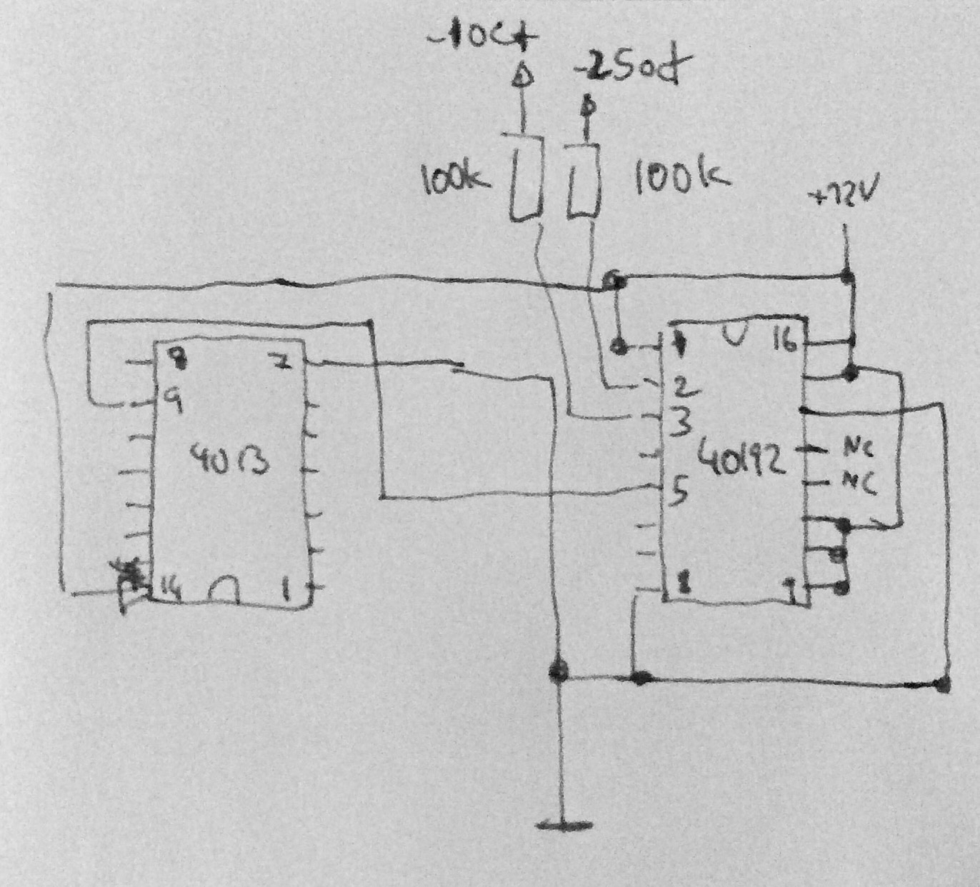
As mentioned above, I also switched the noise selector switch for one with 4 positions, so I could have another option to the -1oct square wave source. Maybe a -2oct wave? Well, not quite.
The distinguishing feature of my frequency divider is that is a BCD counter. BCD meaning: Binary-coded Decimal, i.e. one full cylcle is 10 steps rather than 16, as with a hexadecimal counter decade. And while bit 0 of the counter just puts out a f/2 square wave, bit 1 is asymmetrical:
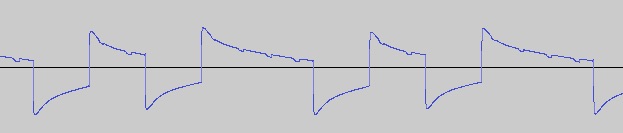
Okay, that’s positively weird. But it sounds interesting – here’s a simple sawtooth, then with some sub-osc added, then with the -2.5oct wave:
To be honest, I might be reversing this part of the mod anytime soon. Or just use a proper 4013 for a proper -2oct wave source.
Coming up next: Overdrive circuitry with the most unlikely amplifier I could find.
Pingback: A Pre-Filter Booster Stage for Jenny - untergeekuntergeek