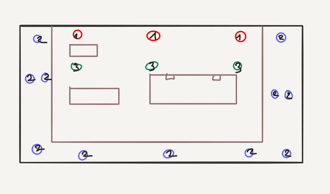
Integrating “That Switch” mod for easier activation of the Reface CP’s hidden Grand Piano patch:
- Remove the spacer next to the Tremolo Depth knob and LED from the control circuit board
- Drill a 5mm hole into the front panel and insert a switch
- Cut the control wire for the selector switch, and connect the ends to the switch
No worries, I’ll go into more of the details as we proceed.
How it works
The “Grand Piano” mode is activated whenever the instrument is switched on with no sound selected – meaning that you can activate it by jockeying the sound selector to a position in between switches before turning it on. It seems to be a test mode Yamaha wasn’t itself fully aware of, but for that, it’s really nice.
These rotary switch gymnastics are nothing you would like to use on stage, as the switch may leave its undefined position any time, and I think it’s not good for the switch either. So soon there were mods disconnecting the toy piano sound that many people don’t like. A much more elegant solution was pioneered by u/lintmachine on Reddit: Add a switch to the panel, and use it to disconnect the switch (or a line of the switch) whenever needed. I basically stuck to that recipe but I think that my way of patching in the switch is easy and elegant.
Putting an additional switch in the front panel
Take the Reface apart. Yes, three types of screws, and MANY of them.
Unplug the cables for the panel in the top of the housing. Once you have removed the panel electronics (18 type 2 screws, knobs and switches can just be pulled off, don’t forget to remove the screws for the the existing rocker switches), you can turn it around and remove one of the plastic spacers. They are just clipped in and can be taken out with (1) a flat screwdriver (2) ease.
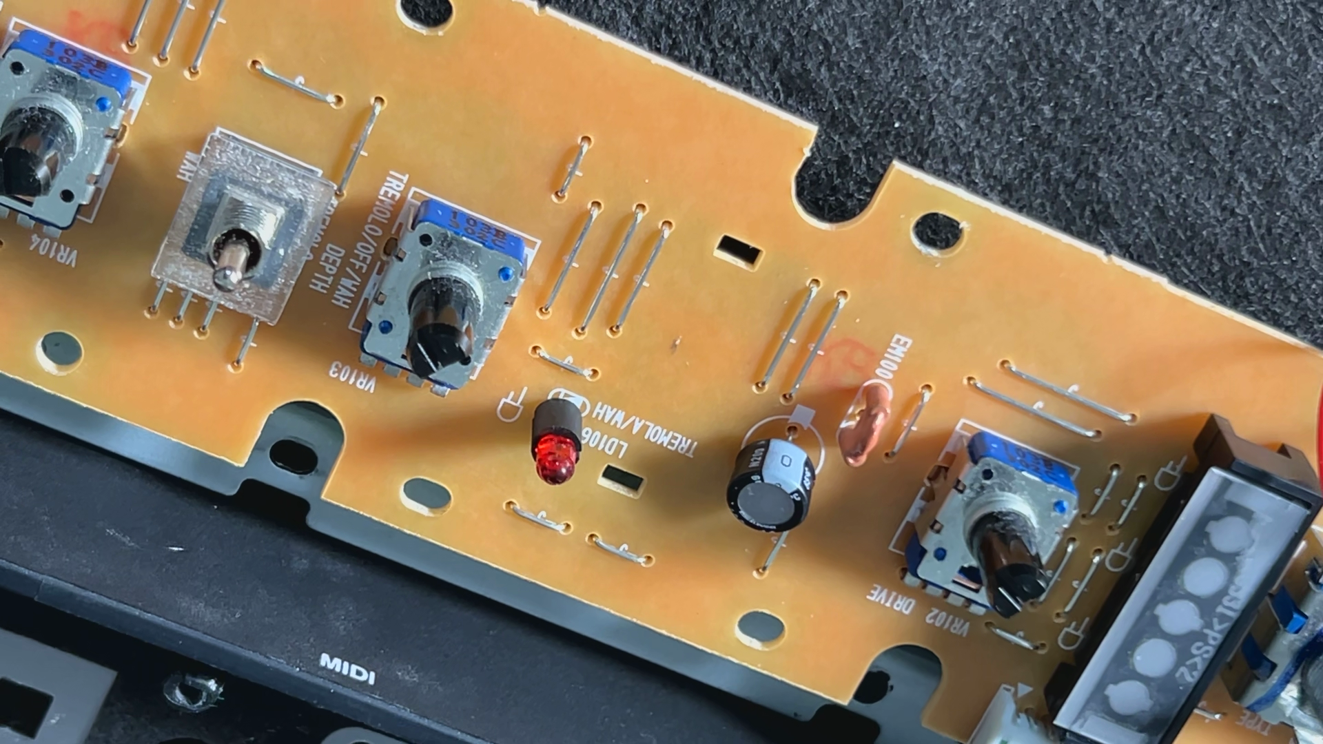
Get a rocker switch to match the Reface CP’s aesthetic. Solder two thin wires of approx. 10cm length to the switch, and bend the wires to reduce the mounting depth of the switch. Drill a hole in the front panel into the center of that blank space where the spacer was sitting.
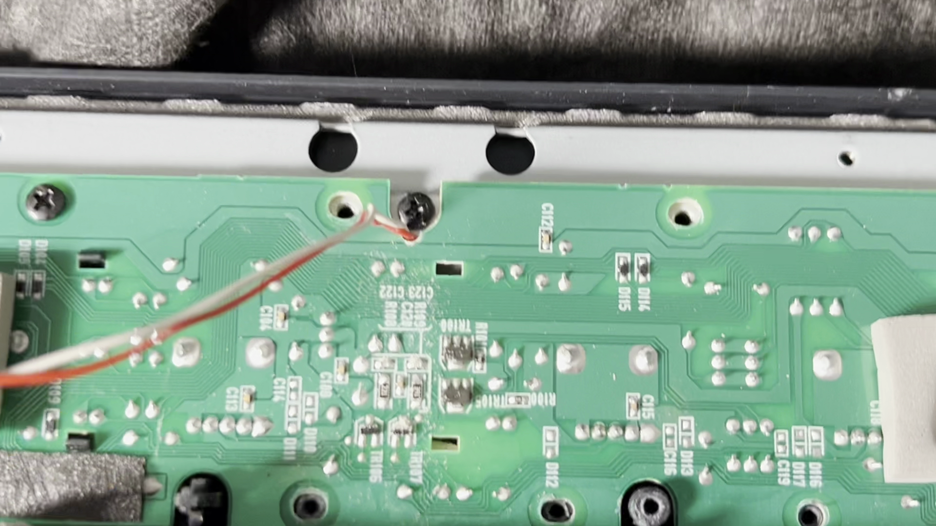
The wires will be led through the notch for the single screw on the front edge, away from the LED. Before reattaching the PCB, take a small file and create a small notch for the cables. Be careful not to mess up the PCB like I did; luckily the ground lane is connected well enough so that I did not do any damage I had to repair. It might also be a good idea to insulate the pins of the switch, and make sure that it does not create pressure on the PCB by being too high. If everything fits well, reattach the PCB, all 18 screws.
The Final Cut
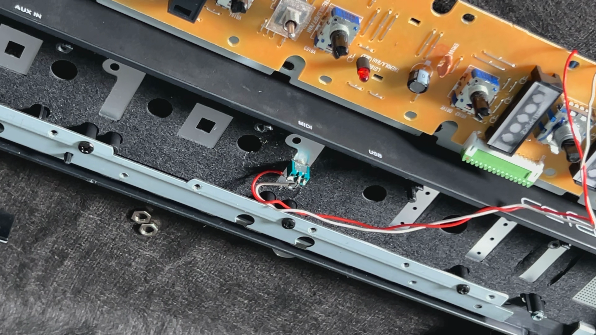
I’ll need you to cut the red wire now! No, seriously, like in Juggernaut (1974). The red wire we are going to cut is the one connecting the rotary sound selector switch, so unless That Switch bridges the cut, the sound selector is disabled. Look at the Reface service manual (PDF on synthxl.com), page 45; it’s line S(0), and it is easy to find as it is connected via a red cable.
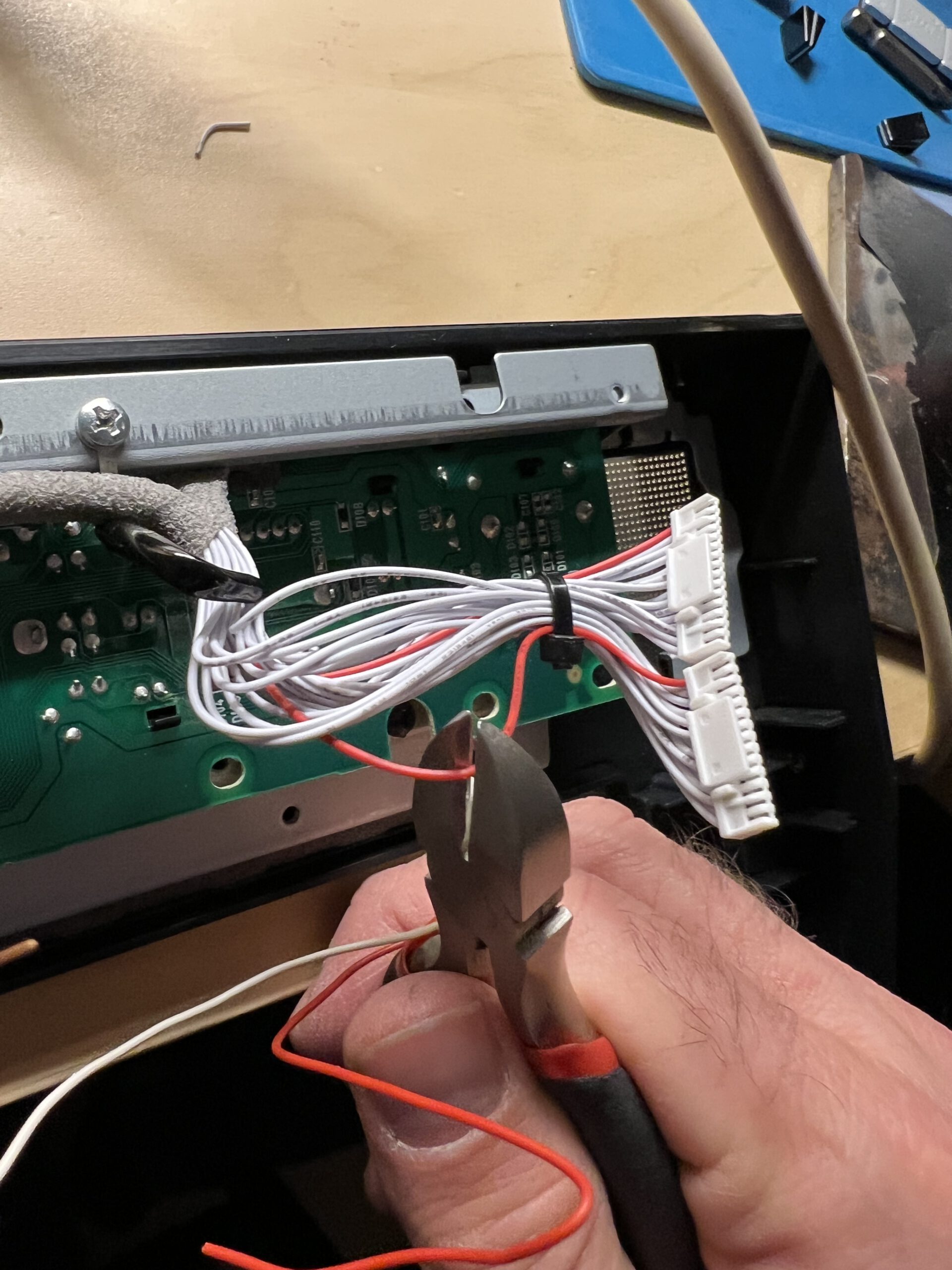
Unfortunately, there are two of them.
The one we need is the one leading from the connector on the left side of the panel PCB all the way to the front connector to the main board; look at the video above. In any case, just reconnect the two ends via the switch – and you are done:
Your Reface now also has – That Switch.
Thanks for that easy tutorial-job for that small thing, it’s work perfect :)