Look: My little old Behringer Eurorack MX1604A mixing console has four insert jacks now, just what you need for a four-channel compressor. After a day spent with sick kids, a little soldering and drilling felt just right.
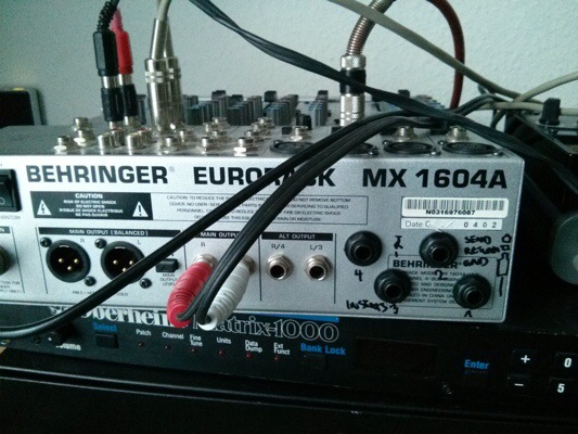
I have been shopping on eBay. Looking for a reverb to go with my rediscovered Oberheim Matrix synth, I acquired a rack containing a Lexicon MX, and a four-channel compressor. Lucky me.
This is when I noted that my mixer has no inserts.
Well, I fixed it. Took me about 3 hours. You need: 4 6.3mm stereo jacks, shielded 3-wire cables, soldering iron and being prepared to use it, a 12mm steel drill.
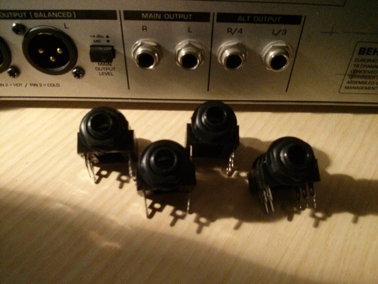
The insert jacks sitting before the unmodified mixer console.
The opened housing. There is enough space on the back plate for connectors, about 40x60mm. Unfortunately, that is not quite enough to fit a row of four with the type of jacks I used.
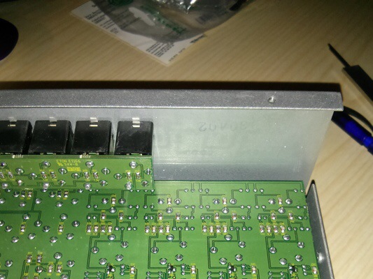
Okay, marked the way out (and back in). But where do we connect it?
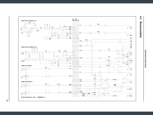
Role model: Successor schematics
Geeks are lazy. I could have spent half a day taking apart the mixer and drawing a schematic, but I asked Google and came up with this: the schematics for the Behringer Eurorack MX 1804X. This is a later model, not quite the same device as my 1604A mixer. The details of the circuitry differ, although they are closely related. And the X version DOES have inserts. So the first thing is to use those as a model:
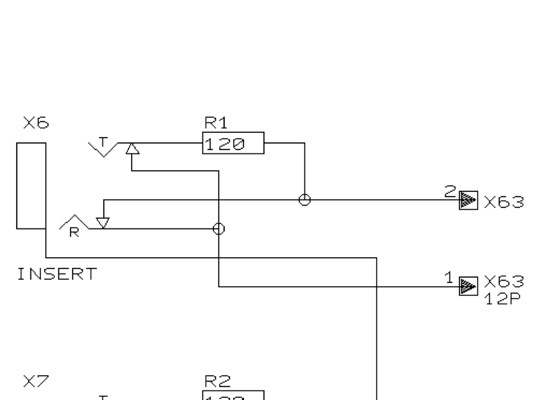
Terminal 2 is Signal Send, Terminal 1 is Signal Return. „T“ is for the tip of the 6.3mm stereo plug, „R“ is for the ring; the v-shaped lines mark the actual connection when a plug is inserted, the little arrowheads mark the switches that are closed when no plug is in the jack. (So it is: Tip – connecting to terminal 2 – is Send, Ring – terminal 1 – is Return, the plug’s base connects to GND.)
Note the 120R resistor in the Signal Send path – when a Mono plug is inserted into the Stereo socket, it would short-circuit Send if it was wired directly to the connector; the resistor protects the mixer circuitry. (I used a 100 Ohm resistor.)
This is my version of it:
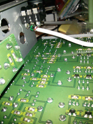
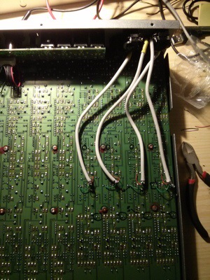
Use shielded cable; I cut up an old USB connection. The cable shield is connected only at the PCB end. I’ve added a bit of shrink sleeve to isolate the shield against short circuits. In this picture you can see why this is necessary; I had to reopen the mixer to fix Channel 1. The holes for the jacks were easily drilled .
The Art of Insertion: Finding the right spot
Where do I cut? Having a look at the block diagram, I decided to cut right after the 3-way EQ.
Comparing with the schematics of the more recent model, you may have noticed that Behringer placed the insert before the EQ, and I was originally going to imitate that, but tracing the equivalent point I found that it wasn’t a good place to cut the signal path. I also used a clue – the Behringer engineers prepared a jumper where you can reconfigure AUX2 for a channel from a post-fader (FX send) to a pre-fader (Monitor send) signal. Tracing the pre-fader signal insertion point, I found my way here:
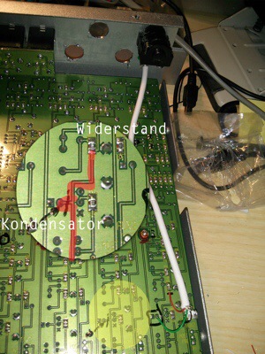
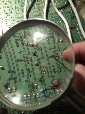
Look at the point marked by the little black arrow – this is a capacitor („Kondensator“) in the signal path pre-fader. The left soldering point is connected to the PRE jumper mentioned above, the right terminal – before the capacitor – is my insertion point. It is connected to a couple of SMD resistors – marked red in the photo – and we are going to cut the connection to the capacitor, solder the Return Signal to it (green wire), and solder the red Send Signal wire to the resistor („Widerstand“) to the right just above.
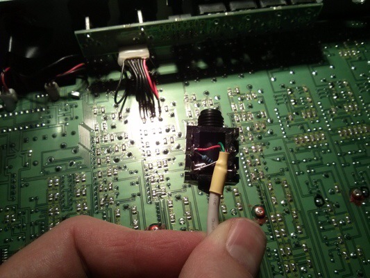
Cutting up the signal path now, soldering the red Send Signal wire to the right capacitor terminal next.
Cut up the PCB line. Solder in the wires to the jacks. Repeat. Test. Be happy.
Is this how they do it?
I’ve tested the modification, using my Korg R3 synth in vocoder mode as an insert effect. It works, although return levels are low.
Please remember that this solution is just a lazy geek’s solution after a very long day. It might have looked different if I had more knowledge of the mixer’s circuits (or, more generally speaking, of analog audio circuitry). If you have inside knowledge of Behringer mixers, you will have a dozen better ideas about how to do this. Please let me know.
Nice work, this is the only good information I could locate from the internet. I plan on doing this type mod for a fostex x 26 four track cassette recorder. But I’m planning to use RCA with a separate send/return after the 2 pre amp sections, so I have the choice of bypassing the pre amps to use other pre amps. I’m just not sure how I’m going to split the signal and where to split the signal.
hi untergeek !
any off-head ideas how to split the stereo output from a synth in two, one signal to the stereo PA line input mixer such as the mx1604, the other to a stereo digital recorder like a tascam or zoom ?
i could use a small behringer 502 or similar mixer, but i would prefer something easier, with no extra power supplies/cable clutter and very portable …
my synths here:
http://www.ise-now.com/music.php
best
Off the top of my head, I would suggest wiring the recorder to the NX5R‘s headphone output. ;)